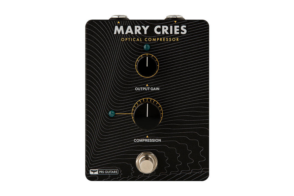
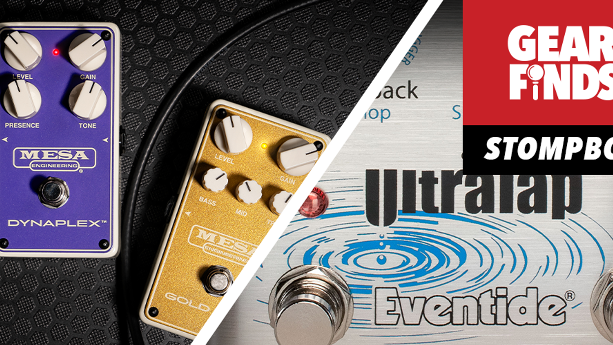
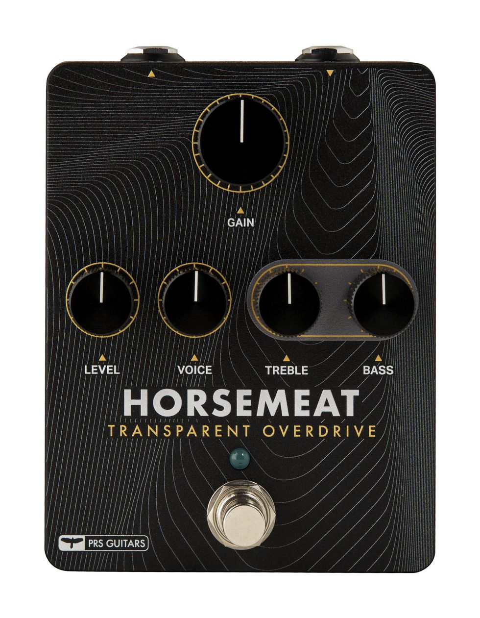
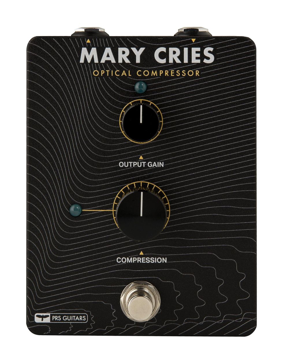
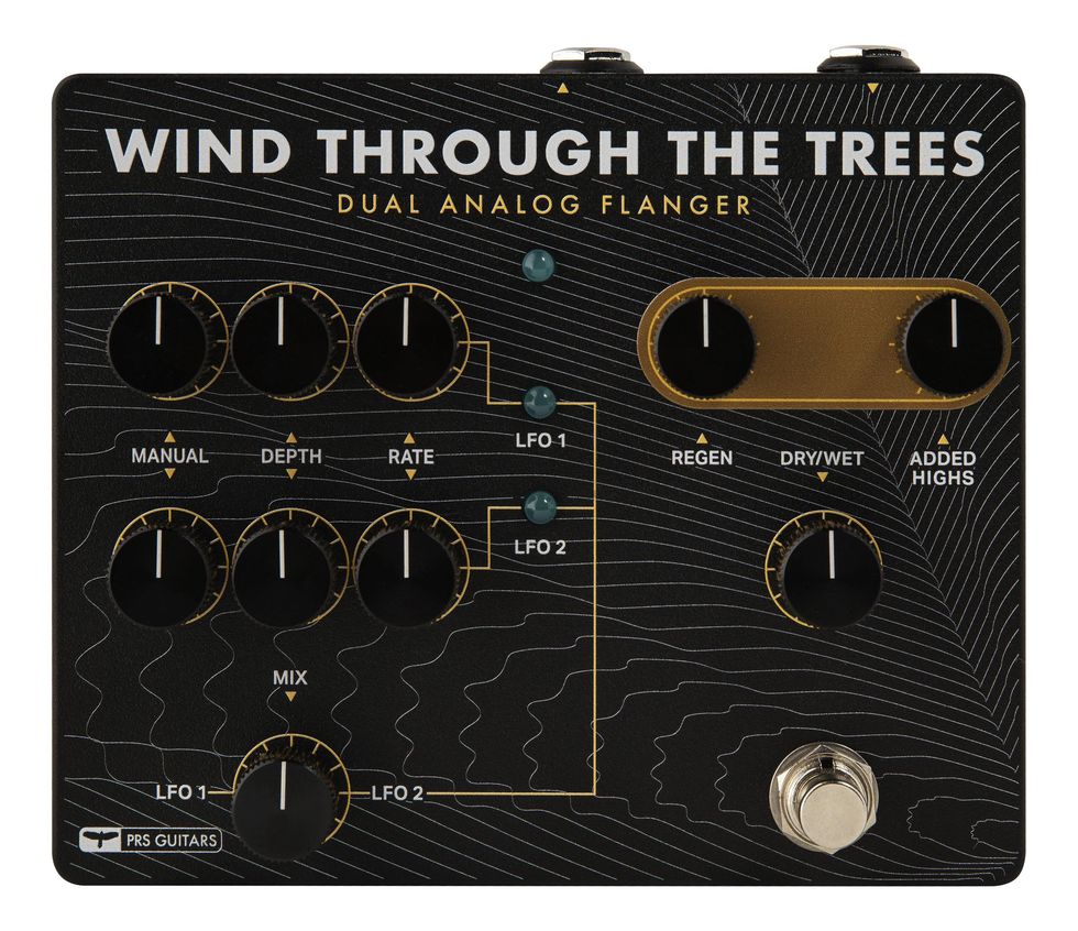
Check out the ALL-NEW PRS Pedals and more in this edition of our Stompbox Gear Finds!
Horsemeat - Transparent Overdrive
The PRS Horsemeat transparent overdrive pedal is designed to enhance your sound without coloring your tone. Horsemeat adds harmonic midrange richness and overdrives without cutting out your high notes – all while giving you more available headroom. It features a robust EQ section so you can dial in your tone and has a wide range of gain on tap. Depending on the setting, Horsemeat can be used as a clean boost, straight overdrive, or even enhance your amplifier’s distortion by slightly pushing the front end of the amplifier’s preamp section.PRS pedals were created to be high-end pieces of audio gear. Designed by PRS Guitars in Stevensville, MD, USA. Made in the USA.
Discoverer Delay
The Maestro Discoverer Delay is a modern analog delay pedal that proudly utilizes legendary analog bucket brigade device (BBD) technology to deliver classic, warm, and inviting delay sounds. The intuitive 3-knob control layout lets users quickly dial up the length of the Delay time (with a range from 20 ms to 600 ms), the amount of Sustain (delay repeats), and adjust the level of the delays in the Mix. A toggle switch engages built-in modulation that applies anything from a slightly saturated, tape-like wow and flutter effect to a heavily pitch-shifted modulation effect to the delayed signal. Two internal trim pots allow the user to adjust the Rate (speed) and Width (sweep range) of the modulation. The true bypass footswitch triggers the LED lights in the bugles in the Maestro logo when it’s on, so you’ll always know when the effect is active.
Tech 21 SansAmp Character Plus Series
The SansAmp Character Plus Series celebrates the unique chemistry between specific historic amplifiers and specific historic pedals, and cleverly unites them together in single packages:
- Screaming Blonde = Fender-style + Tube Screamer-style
- English Muffy = HiWatt-style + Big Muff-style
- Fuzzy Brit = Marshall-style + Fuzz Face-style
- Mop Top Liverpool = Vox-style + Rangemaster Booster-style
Each of the individually-voiced Character controls sweep through an entire spectrum of eras within their particular amp style. Screaming Blonde tones range from the ‘50s Fullerton to blackface and silverface. The English Muffy spans from classic UK rock to prog rock. Fuzzy Brit goes from classic hard rock to all current rock genres. The Mop Top Liverpool embodies the British invasion through “Bohemian” rock.
These 2-channel multi-function pedals are each like having a stompbox within a stompbox. You can use the SansAmp amplifier emulation on its own or just the effect on its own. The all-analog SansAmps Character Plus Series pedals can be used as stand-alone pre-amps to drive a power amp, a studio mixer, or a PA system, or to complement your existing amp. Other features include built-in speaker simulation individually tuned to match each of the speaker/cabinet configurations associated with each amplifier type; 3-band active EQ, XLR Output, included 9V DC Power Supply. Rugged all-metal housing measures 7.75”l x 2.5”w x 1.25”h and weighs just 12 oz.
EARTHBOARD Pedalboard System
Never before has an effects pedalboard been so effortless to build and painless to change or rearrange on the fly - So you can Focus on the Music, Not the Set-Up!
Our game-changing design incorporates Rare Earth Magnets ("cupped" so there is no risk to your pedals!) and a long-lasting Battery to give you the neatest, cleanest sounding and looking rig! All of the hassles of using a traditional board are gone. No more messy cobweb of cords and cables. No need to look for outlets and extension cords. No need to deal with dirty noise at gigs. Increase voltage and isolate those "picky" pedals without adding more mess and expense of separate power bricks and adapters. NO MORE SOUND OF RIPPING VELCRO!!!
Here's what's possible with EARTHBOARD:
- Your choice to use our Battery or AC Adapter
- Jacks are on both sides to accommodate YOUR style and the unknowns of the gig space
- All of our power supplies have built in circuit protection to safeguard your pedals
- Built-in cross board audio patch cable saves you money and the hassle of finding the right length cable to connect your top and bottom rows of pedals
- Ability to power large pedals off the board to maximize board real estate - make room for one more pedal!
- The built-in, under mounted, Blue LED lights enhance visibility and the "cool factor"
- Daisy-chain multiple boards and power them all with a single battery
- Rearrange or add pedals on the fly, between sets, in a matter of seconds
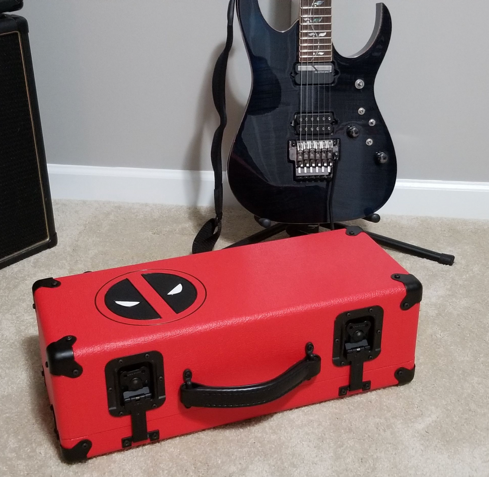
Gator Cases G-TOUR Large Pedal Board with Wheels
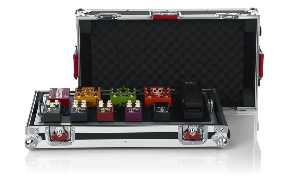
Large tour grade pedal board and flight case for 10-14 pedals with removable 24″x11″ pedal board surface and inline wheels
Features:
Pro-grade shock absorbing EVA foam interior
Removable pedal board surface 24" x 11"
Two (2) rubber-gripped handles for easy lifting in and out of the case
3M Dual Lock» hook and loop fastener for pedal installation
Cable and accessory storage under the removable pedal board
Retractable tow-handle and inline wheels
Plywood construction with aluminum edging to create a secure closure between lid and base
Protective ball corners at vulnerable points
Commercial grade Gator red signature hardware
Lockable latches
Spring-loaded rubber gripped handles
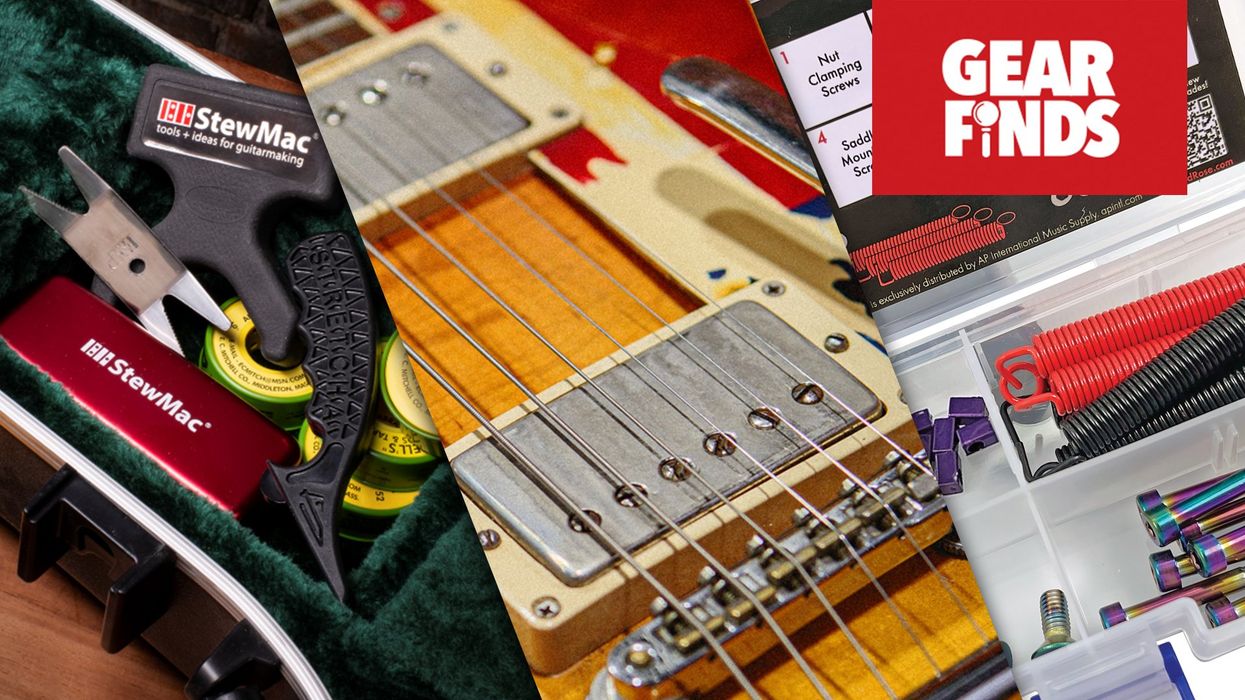
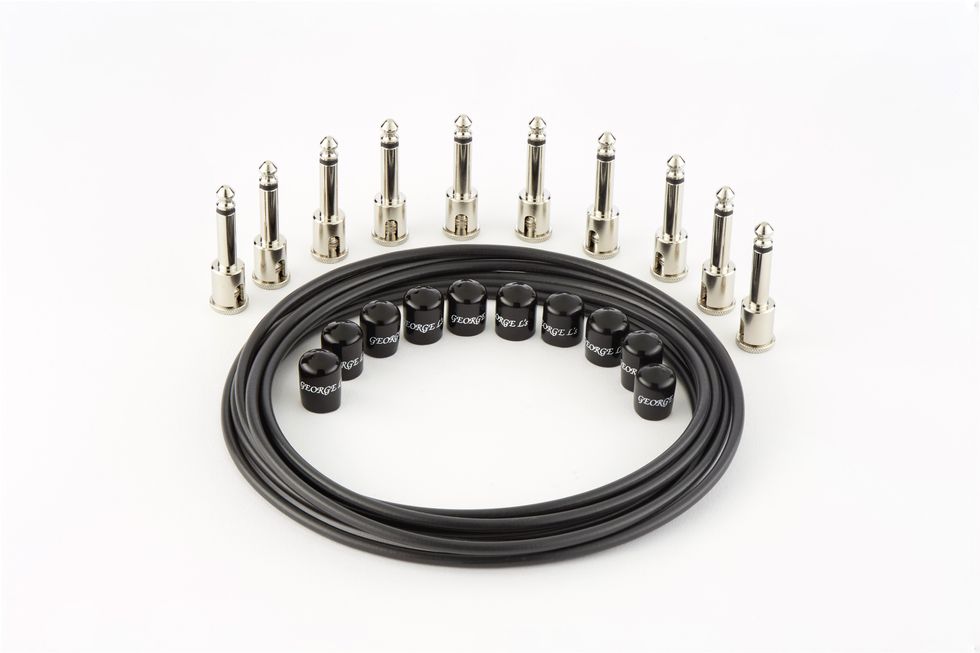
George L's Effects Cable Kits
Enhance the tone and clarity of your pedalboard with award winning sound.
The George L’s effects kit.
The kit comes with 10’ of cable, 10 right angle plugs and 10 stress relief jackets.
Available in black, vintage red and purple.
As easy as 1, 2, 3 no soldering!
Cut, poke and screw your way to 47 years of sound excellence.
Our much-loved former columnist Jeff Bober returns to explain how to check and reset the bias of your amp’s output tubes—and delivers some potentially shocking warnings about a few common but dangerous techniques.
Hello again, Premier Guitar readers! It’s your old bud Jeff here, author of the once popular Ask Amp Man column. Editorial Director Ted Drozdowski asked me if I would be interested in writing about bias, and, of course, I said, “Sure, I know a thing or two about that!” So here I am, temporarily returning to these pages. Now, let’s get started.
What exactly is bias? Bias is prejudice in favor of or against … oh wait, wrong kind of bias. I think he wanted me to write about bias in a tube amplifier, which is far less polarizing.
Bias, as defined in the RCA Radiotron Designers Handbook, is “voltage applied to the grid [of a tube] to obtain a desired operating point.” Well, that is the most basic explanation, but for the most part it is good enough and pertains to the majority of tube output stages in our favorite tube guitar amps.
Setting the bias adjustment controls to these listed voltages in no way guarantees that your amp is properly biased.
Besides “applying” a voltage to a vacuum tube, however, biasing can occur in another way as well. There are quite a few amplifiers, such as a Vox AC15 and AC30, any of my Budda and EAST designs, and even most of the early, low-wattage amplifiers of the tweed era that use what’s known as a “cathode bias” design. This is where the current flowing through the tube (which attains the aforementioned “desired operating point”) is not set by the voltage “applied” to the grid of the tube, but is instead set by the resistor in the cathode leg of the tube. It’s a bit more complicated than that, but the result is an amplifier whose output stage is “self-biasing.”
Most amplification devices, including transistors and even preamp tubes, need to be “biased” in order to perform properly, but this type of biasing is fixed in the design parameters of the circuit. In the case of the preamp tubes in your guitar amp, bias is based on the value of the cathode resistor, among other things. But that’s enough design theory for today. Let’s get back to the core task of biasing the output tubes in most guitar amplifiers.
First, the bias voltages you see listed on many schematics, such as 52V on a black-panel Fender Twin Reverb or 51V on a Marshall 100W Super Lead schematic, are merely approximations of the voltages that should be expected in that area of the circuit. Setting the bias adjustment controls to these listed voltages in no way guarantees that your amp is properly biased. Tube bias is also dependent on the high voltage (or B+) applied to the plate of the output tube, which can vary within tolerances of the transformers as well as in the AC line voltage fed to the amp. (This is why amps can sometimes sound better in one room or club than others.)
But even more important to understand is that tubes produced in different factories across the globe will bias up differently! What I mean by this is, if you properly bias a set of output tubes—let’s say 6L6s made in Russia—and then you swap them out with a set made in China, in the same amplifier without changing the setting of the bias control, the end result will almost always be a different bias reading. This is why it’s always best to have checked and reset the bias whenever output tubes are replaced. Now, how do we do that?
The Preferred Method
Fig. 1
There are several different ways to measure output-tube bias current at idle. The safest method is to use what is commonly called a bias probe (Fig. 1). This is a device that is inserted between an output tube and its socket. (I typically make my own bias probes, but if you simply search “bias probe” online, you’ll find plenty to choose from. If you already own a multimeter, you can simply purchase the probes, but there are also options to purchase a full system with either a digital or analog meter, should you need it.) This device breaks the connection between the cathode (which is the metallic electrode from which electrons are emitted into the tube) of the tube and its ground connection, and inserts a small value resistor in between. It then allows the voltage across the resistor to be read. The resistor is typically 1 ohm and the resulting voltage drop across it is in millivolts (mV), so no chance of shock here. This provides a true and accurate measurement of the actual current flowing through one tube. Then, you set your bias and you’re done!
But even more important to understand is that tubes produced in different factories across the globe will bias up differently!
Ah, but wait! How do you set your bias? Let’s learn a bit more. Most tube amplifiers, if they are not cathode-biased designs, have some way to adjust the output-tube bias. One longstanding exception to this are most Mesa/Boogie amps. The bias voltage in these amps is not adjustable, which is why Mesa suggests only purchasing their tubes for their amps, because they are designed to fall within the acceptable bias range for their amps. This adds a certain degree of confidence for owner servicing, although, of course, it limits your options.
Let’s take a look, however, at a typical Fender or Marshall bias control. Most older Fenders have a pot with a slot for a screwdriver mounted to the chassis in the area of the power or mains transformer, while most older Marshalls have their bias pot mounted on the circuit board. (You might want to go online to look at schematics for your amp to help you find it.) Either way, this is where you’ll make your adjustment.
Fig. 2
To get started, you’ll most likely need to pull the chassis and place it in a stable work environment. Insert the bias probe device between one of the tubes and the socket (Fig. 2). Make sure all the volume controls are set to zero, turn the amp on, and let the tubes warm up. It’s also good to try to have a load on the speaker jack—whether a speaker or an appropriate resistor or load box. This is not 100 percent necessary for just setting the bias to a particular number, but sound checking is one of the ways I like to make the final adjustments, so being able to connect the speaker to the chassis while it’s on the bench is certainly a necessity for me.
Now, where to set the numbers? There are certainly more than a few opinions floating around on the interwebs about what optimal bias settings are. Some engineering types will tout 50 percent maximum plate dissipation or 70 percent maximum dissipation, and while it may look good or make sense on paper, I’ve heard the result of guitar amplifiers designed by the book to optimal specifications … and to me they sound, well, less than optimal. It may work in the hi-fi world, where perfect sound reproduction is the goal, but guitar amplifiers are in the sound production business, so it’s a bit different. (In the most basic terms, maximum plate dissipation is the amount of power the plate of the tube is designed to deliver.)
Different types of output tubes have their own acceptable range of bias current. There are so many variables at play that there is no “correct” number. The plate voltage in the amplifier, the output transformer’s primary impedance, and the country of origin of a tube all factor into how it interacts with the voltage and output transformer to define what the optimal bias current will be. Below are the average ranges for some typical octal output tubes:
• 6L6: 25–35 mA
• EL34: 30–40 mA
• 6V6: 18–25 mA
• 6550: 35–45 mA
• KT66: 30–40 mA
Fig. 3
These should be the ranges in which these tubes will perform and sound the best, and they can be accurately measured with a digital multimeter. The best way for you to decide what setting is best for you is a combination of the reading on the meter and your ears! Using the bias control, set the bias to somewhere in the ranges given above (Fig. 3) and play the amp. Note: Some amps will act funny and develop horrible noises (parasitic oscillations) when a bias probe is in place while the amp is being played. If this is the case, you’ll need to remove the bias probe each time you play the amp.)
Move the setting a couple mA in one direction or the other and play again. Don’t expect extreme changes; that’s not what we’re looking for. Listen for subtle differences. Is one setting a little more or less harsh? Is the bottom end too soft or flubby? Is the amp as clean as you want it? Sometimes these little subtleties are what make one amp sound and feel better than another!
Most older Fenders have a pot with a slot for a screwdriver mounted to the chassis in the area of the power or mains transformer, while most older Marshalls have their bias pot mounted on the circuit board.
Also, you should be doing this at the volume you would typically use onstage or in the studio. You may not notice much change if your volume is at 1, but you want to optimize the amp for the way you will be using it.
Eyes Wide Open
Fig. 4
Knowing the ballpark bias numbers is good, and adding your ears is even better, but I also like to see what I’m hearing, so I always incorporate an oscilloscope when I’m setting the bias on an amp. I mentioned crossover distortion above, and when it comes to setting up amps for today’s pedal-hungry players, I find that setting the bias to where there is just a hint of crossover distortion at full output is what works best. Fig. 4 is what that looks like on the oscilloscope. This keeps the amp very clean and makes most pedal users happy.
By the way, here’s a mini primer in crossover distortion. In a push-pull output stage, which is found in most amplifiers with two or more output tubes, each tube (or pair of tubes) is responsible for amplifying at least half of the audio signal. If the tubes are not biased properly, one tube (or pair) will stop amplifying before the other tube (or pair) start amplifying. This will create crossover distortion. Proper biasing will allow the two halves to interact correctly. It’s like a nice firm handshake between both halves.
Beware These Old-School Methods
Let’s look at a couple popular methods that I do not recommend, but are worth discussing because they are, nonetheless, common. The first is: With the amp off and output tubes removed, use a multimeter to measure the resistance of each half of the primary side of the output transformer. This would typically be from the center tap to each side of the primary winding.
In the most basic terms, a transformer is a bunch of wire wound around a steel core. On the primary side of an output transformer, the center tap is the electrical “middle” of this long length of wire. This is typically where the high voltage is applied. The ends of this length of wire are connected to the plates of the tube, thereby applying the high voltage to the tubes. As an example, typically in most Fender amps, the center tap is red, and the ends of the primary windings are blue and brown.
Fig. 5
Next, install the output tubes, turn the amp on, and measure the voltage drop across each half of the output transformer with the amp at idle in operational mode (Fig. 5). Voltage divided by resistance will give you the DC current through the tubes. For example, 1.17V / 15.8R = 0.074, or 74 mA. The numbers I used here were actual measurements in one side (one half) of a 100W amp using four output tubes (two per side). So, divide the 74 mA by two, and you get an average of 37 mA per tube.
Next, you can try the shunt method. This requires a multimeter that can read DC current in milliamps (mA). Connect one meter lead to the center tap of the output transformer and the other lead to the output transformer’s primary side. Typically, in most amps using octal tubes (6L6, 6V6, EL34, 6550, KT88, etc.), this will be pin 3 on any output tube socket. Turn the amp on and, in operating mode at idle (i.e., volume off), measure the current across that half of the output transformer. For example, if your measurement is 72 mA and it’s an amp that utilizes four output tubes, the current measured is for two of those tubes, so once again divide by two to arrive at 36 mA per tube.
I’ve heard the result of guitar amplifiers designed by the book to optimal specifications … and to me they sound, well, less than optimal.
Both of those methods are very old school and still in practice, but I wouldn’t use either for two reasons: 1) I don’t believe they’re very accurate, and 2) they’re dangerous! You’re probing around inside the high voltage area of the amp, and one slip will either take out a fuse, take out a tube, take out your meter, or, worse case, let you know exactly what 450V DC feels like! So, although these methods are used, let’s just say no here.
Some Personal Insights
I’d also like to add a little personal experience to this procedure, based on decades in the biz. Back in the day, when I began servicing and modifying gear, guitarists were regularly playing 50- and 100-watt amps. (Everybody looked at me like I had three heads when I came out with the 18-watt Budda Twinmaster, but that’s a whole other story.) There were some overdrive and distortion pedals around (now all vintage), but certainly not the pedal proliferation we have now, so players were pretty much guitar, cable, amp … go! In these situations, I would most times run the tubes with a pretty hot bias so the amp would be fatter and overdrive a bit earlier and easier, as a decent percentage of the overdrive was developed by pushing the output tubes. As time went on, output attenuators became more popular, so amps could be pushed hard, but at more manageable volume levels. That was still a good scenario for a hotter bias of the output tubes in high-power amps. Eventually, players started playing lower-power amps, so they could open them up and get great output-tube distortion at lesser volumes. The problem is that hotter-biased low-power amps tend to get mushy and have less definition when pushed hard, so a more moderate bias setting is preferred here—just enough so there is no crossover distortion. Move up to today’s scenario and you’ll find that almost all overdrive and/or distortion is typically coming from a pedal. In that case, an amp is nothing more than an amplification device for pedals.
So, that’s what I’ve learned about tube-biasing from my decades of experience. But the bottom line is, there is no absolute right or wrong settings when it comes to biasing an amp. Keep your ears open and go with what sounds best to you.Wong Notes is presented by DistroKid.
Use this link for 30% off your first year.
Soulive, Lettuce, Tedeschi Trucks, and most recently, Stanton Moore and Branford Marsalis—that's a short list of some of the acts Eric Krasno plays and has played with throughout his career. From one funk guitarist to another, Cory sits down with Eric to talk what it means to play the right amount of notes when jamming, what it takes for Eric to absorb and learn so many different genres, and the impact the jam band community has on its musicians. Thanks for listening to this season of Wong Notes, and be sure to catch the next!
EHX releases their take on the extreme '80s distortion.
The Electro-Harmonix Hell Melter takes distortion to its extremes in their take on the cult classic chainsaw distortion pedal with expanded controls and tonal capabilities. This distortion circuit originally designed as the ultimate in high-gain is now known for the death metal sounds of the likes of Sweden’s Entombed, and the shoegaze wash of My Bloody Valentine. Surprisingly, it’s even been at home in the rig of David Gilmour.
The EHX Hell Melter enhances on the original design with many modern updates and features. More overall output volume is available on tap than the original circuit. The active EQ expands the original single highs control, which controlled peaks in both the treble and upper-mids, into a HIGH control and parametric MIDS LVL control with adjustable MID FREQ ranging from the signature high-mids bark to a low-mids growl. The LOW control rounds out the powerful 3-band EQ. A mode toggle goes from NORM to the new BURN mode which opens up the sound of the pedal significantly by switching to more open clipping options and boosting the internal voltage for more headroom. Additional new features include a noise gate and DRY LVL control, which is useful when using a bass guitar or using an already dirty amplifier. A foot-switchable BOOST section increases the overall gain and volume of the pedal. DISTORTION and LEVEL knobs control the overall gain and output volume of the pedal respectively.
Electro-Harmonix Hell Melter Distortion Pedal
The Hell Melter comes equipped with an EHX 9V power supply and buffered bypass. It features a USA street price of $176.66.
For more information, please visit ehx.com.