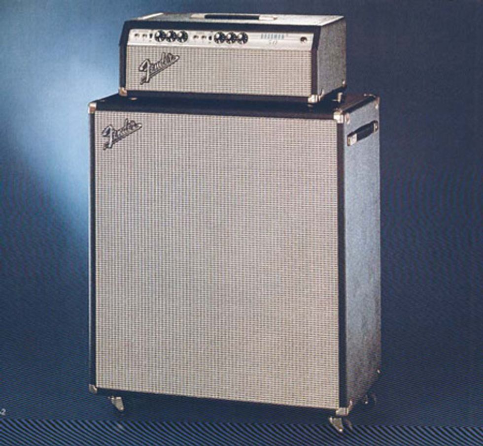
A Bassman 50 rig as pictured on page 52 of Fender’s 1972 catalog.
Photo courtesy of FMIC and vintageguitars.org.uk.
Jeff,
In the December issue, I read about the mods you can make to a Fender Bassman 10 [“Souping Up a Bassman 10,” Dec. 2010 PG]. I’d like to know if those mods could also apply to an early ’70s Bassman 50? The amp has already been re-tubed and re-capped (including filter caps), but all the tone is focused in the mid frequencies. It lacks the typical Fender high-end and low-end. Can you help? —Dennis
Hi Dennis,
Glad you enjoyed the column on the Bassman 10. Just FYI—and to anyone else that is considering those modifications—we published a correction for that column with regards to a .0047 μF capacitor. The corrected instructions should read: Another change you can make is to locate the .0047 μF capacitor that connects the Treble pot wiper to the CW leg of the Volume pot. This cap is limiting some of the Studio channel’s frequency range. Removing it and replacing it with a short wire will give the channel additional punch. So, with that out of the way, let’s get to your question.
After an extensive and frustrating search, I have to tell you that a schematic for the amp sold as the Fender Bassman 50 does not appear to exist. While there are schematics for Fender Tweed-era Bassmans, Bassman 10s, Bassman 70s, Bassman 100s, Bassman 135s, 12-watt bass amps, 200-watt bass amps, and even Fender’s behemoth 300-watt bass amps—a schematic specifically labeled “Bassman 50” is simply nowhere to be found.
But after seeing a picture of a Bassman 50, I can surmise that it most closely relates to a standard-style Bassman of the ’60s and ’70s. Since there are at least five or six schematics that encompass this era, it’s impossible to tell which might be the appropriate schematic for your amplifier. The best advice I can give you is to go through the modifications in my Bassman 10 column, and see which are applicable to your particular amp.
Even though I believe most guitarists who play through Fender Bassmans do so specifically because they don’t sound and respond like a typical Fender guitar amp, there are a few more suggestions I can give you regarding ’60s and ’70s Bassmans that may make them to your liking.
As always, this work is very dangerous—it can even be lethal. So if you are not familiar with the inner workings of a tube amplifier and the possible hazards involved, please have this work performed by someone who is.
First, locate the 100k plate resistors on pin 1 of the first two preamp tubes (V1 and V2). These resistors may have a capacitor in parallel (mounted across them). The Normal channel may have a 500 pF and the Bass channel may have a 0.01 μF capacitor. Removing these caps will immediately brighten up their respective channels.
Now locate the components attached to pin 6 of V1 and V2. Each should have a 100k plate resistor attached to them. You can leave these alone. Also attached to pin 6 on most models will be another resistor. These are the channel mixing resistors. In most cases, these will both be 220 kΩ resistors, and they can also be left alone. If the resistor associated with the Normal channel is a 470 kΩ, change it to a 220 kΩ. This will give that channel a bit more punch and fullness.
By the way, in most of these Bassman-style heads, both channels will be in phase, which means that you can run your guitar signal into both channels simultaneously— and blend the two together for the best overall tone and response. If, however, the mixing component from pin 6 of the Bass channel is a capacitor, the channels are out of phase in this model, and you’ll get phase cancellation at various frequencies if the two channels are combined.
Now let’s move a bit further down the line to the phase inverter. Most amps will have a resistor and one or two 0.01 μF or 0.1 μF capacitors connected to pin 2 of V4. If your amp is like this, it’s fine and can be left alone. If your model has a 500 pF cap connected to pin 2, this should be changed to a capacitor in the 0.01–0.1 μF range. This will give the amp a considerable increase in fullness and body.
This same area is where the negative feedback loop is employed. There is a lead coming from the tip terminal of the output jack. Follow it to the first resistor it is connected to. If it is connected to an 820 Ω resistor, there is nothing more to be done. If it is connected to a 47k resistor, in most models this resistor will have a 100 pF capacitor in parallel with it. This cap is adding additional high frequencies to the negative feedback signal. Removing this 100 pF cap will bring just a tad more brightness back to the amp.
There you have it. These changes, along with any applicable changes from the “Souping up a Bassman 10” column should give you a pretty good sounding Bassman 50. Hey, it will probably sound better—after all, it’s 40 more than 10! Enjoy.
 Jeff Bober is one of
the godfathers of the
low-wattage amp revolution,
co-founded and was
the principal designer for
Budda Amplification. Jeff recently launched EAST
Amplification, and he can be reached at
pgampman@gmail.com.
Jeff Bober is one of
the godfathers of the
low-wattage amp revolution,
co-founded and was
the principal designer for
Budda Amplification. Jeff recently launched EAST
Amplification, and he can be reached at
pgampman@gmail.com.
![Rig Rundown: The Black Crowes’ Rich Robinson [2026]](https://www.premierguitar.com/media-library/youtube.jpg?id=66952027&width=1245&height=700&quality=70&coordinates=0%2C0%2C0%2C0)