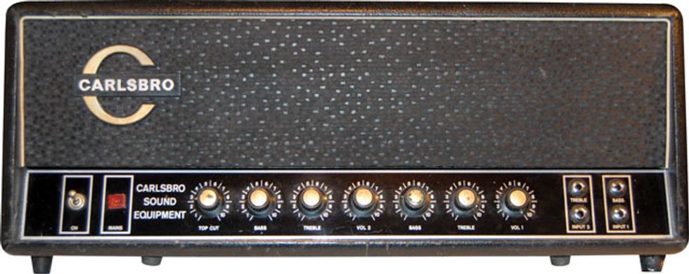
 A rare 60-watt Carlsbro CS60TC.
Rick Hogue, a good friend of mine who owns Garrett Park Guitars in Annapolis, Maryland, recently acquired an older Carlsbro amp head. He loved its sound and asked me to take a look at it. It turns out he has a black plexi-panel, 60-watt Carlsbro CS60TC, in very nice shape. In all the years I’ve been servicing amps, this is the first time I’ve run across one of these, so I was curious. Carlsbro amps were built in Nottingham, England, and seem to be more rare in the USA than any other British amp.
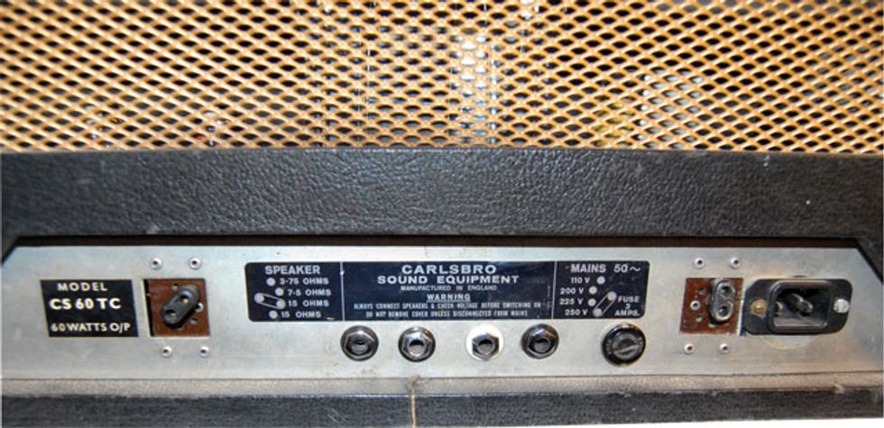
The amp has two discrete channels, Bass and Treble, each with a low- and high-level input. The amp’s only controls are Volume, Treble, and Bass for each channel, along with a global Top Cut knob. A power switch and pilot lamp round out the front panel with the noticeable lack of a standby switch. The rear panel is very minimal as well. An AC socket, that appears to have been changed from a British Bulgin to a US IEC jack, a voltage selector, a couple of speaker output jacks and an output impedance selector with 3.75, 7.5 and 15 Ω settings. Definitely old-school British! Rick offered to let me take it back to the shop and see what made it tick.
Before I disassembled this rarity, I decided to try it out first. Very nice—the CS60TC sounded open and percussive with just the right balance of clarity, growl, chime, and grit. Think plexi meets Hiwatt, with a tilt towards the latter. What it lacked in front-end gain, it made up for in tone.
When I pulled the chassis, I didn’t see anything out of the ordinary. So what makes this amp sound the way it does? The cathodes of both V1 and V2 use 1k Ω resistors and 64 μf bypass capacitors. Seeing that indicated there should probably be more front-end gain than the amp was delivering. A quick look at V1 revealed the first anomaly— someone had installed a 12AT7 in this position. According to this amp’s schematic, the preamp tubes should be all 12AX7s. A quick change to the proper tube resulted in ... nothing more than a moderate increase in gain.
 The rear panel with its old-school British design.
Measuring the plate voltages helped make sense of this. The plates of V1 read approximately 125V DC. High enough for the tubes not to be “starved” and artificially distort, but low enough to achieve less-thanmaximum gain. But this can’t be the only reason the Carlsbro sounds the way it does. What else would I find?
Moving on to the phase inverter, there seemed to be nothing exceptional here, either. The only surprise was a 68k feedback resistor. Generally, the output stage will be “cleaner” and have less apparent gain when a low value feedback resistor is used. This setup however, in this amp, seems to yield a nice balance between clean and mean, depending on how hard the amp is pushed.
I then took a look at the output stage to find out what’s lurking under those EL34s. The first thing I noticed was that someone had added a 470 Ω resistor in series with the stock 1k screen grid resistors. The net effect of this should be a slight drop in the DC voltage at the screen grids, which would neither substantially affect the output power nor tone of the amp, but I decided to verify this. Switching back to the stock 1k resistors did indeed increase the output a miniscule four watts, and there was a very slight difference in the tone. At higher volume settings, the amp had just a bit more fullness to it, but at lower volumes, the amp sounded slightly better to me with the additional 470 Ω resistors in place. It had just a bit more jangle. This reminded me of what I always tell customers regarding amp mods: “Whenever you change something, there’s always a tradeoff.”
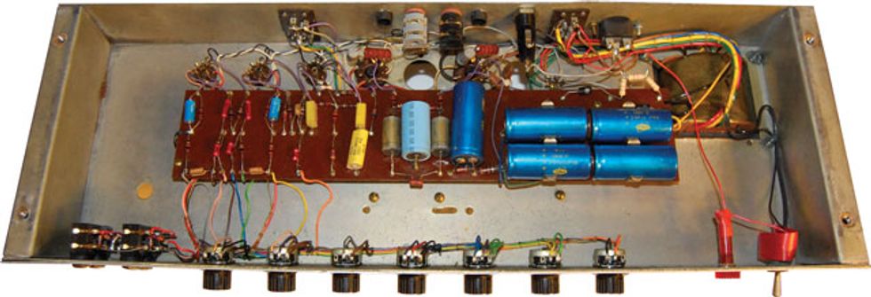
 Nice vintage handwiring!
I also saw the bias supply had been previously repaired. The value of the stock dropping resistor from the HT winding to the bias diode is 180k Ω. Someone, I’m sure doing the best they could with the parts on hand, elected to place three 47k resistors in series (yielding a 141k total value) to replace the unusual value 180k bias resistor. The result was that the bias voltage rose from the schematic’s stated voltage of -35V DC to a much greater -50V DC, causing the amp to be substantially over-biased. Lowering the bias voltage to the schematic’s level removed all the crossover distortion present in the output signal, but set the idle current of the output tubes at around 65 mA. This was a bit too high in this amp, in my opinion. Adjusting the bias resistor to a value of approximately 160k placed the tubes at a more respectable 40 mA of idle current and definitely improved the amp’s overdriven characteristics at higher volume levels. Chalk up another validation for properly biasing output tubes!
Well, there you have it—hope you enjoyed our tour inside a rare and fine-sounding amp.
 Jeff Bober is one of
the godfathers of the
low-wattage amp revolution,
co-founded and was
the principal designer for
Budda Amplification. Jeff recently launched EAST
Amplification, and he can be reached at
pgampman@gmail.com.
Jeff Bober is one of
the godfathers of the
low-wattage amp revolution,
co-founded and was
the principal designer for
Budda Amplification. Jeff recently launched EAST
Amplification, and he can be reached at
pgampman@gmail.com.


![Rig Rundown: Russian Circles’ Mike Sullivan [2025]](https://www.premierguitar.com/media-library/youtube.jpg?id=62303631&width=1245&height=700&quality=70&coordinates=0%2C0%2C0%2C0)