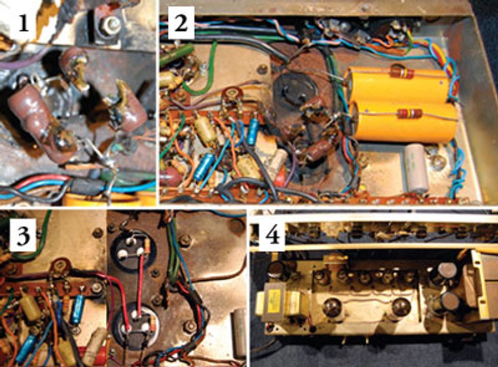
1. Ceramic resistor meltdown? This amp was on fire! 2. Inspecting the chassis—schematic in hand—I spot improper caps and resistors. (Hint: Look at the yellow cylindrical caps.) They’ve got to go! 3. The new dual 100 μf caps and divider resistors are installed. 4. Sweet! Top view of the Concord’s chassis after I’ve installed the new caps and tubes.
Last month, I described beginning what seemed like a normal repair of a Sound City Concord 2x12 combo [“Rare Bird—the Sound City Concord Combo,” April 2012]. Blown fuse, scorched tube sockets—these signs indicated typical high-voltage havoc. Normally I’d replace the tube sockets, check for and replace any damaged grid and screen grid resistors, install and bias a new set of output tubes, give the amp a thorough bench check, and then rock out with it for a while to see if it’s ready for the stage.
Well, once I pulled the chassis on this cool vintage combo, I was stunned to see a couple of melted ceramic resistors. Now I’m no chemist, but doing a bit of research I learned that ceramic can have an operating temperature of between 3,300 and 5,400 degrees Fahrenheit. This means it melts at an even higher temperature! How could this have happened without incinerating the amp?
My initial inspection revealed that the output tube sockets would need replacing, but what the heck was going on with these ceramic resistors? Also in the area of the resistors were two axial filter capacitors, along with the chassis-mounted can capacitors. The can capacitors looked like original equipment, the axial caps definitely did not. Whoever installed these replacement caps also installed 220k voltage-divider resistors in parallel with the capacitors—a good thing to do, as these resistors produce an even voltage split across each of the two capacitors in series. But looking at the schematic, I realized these resistors didn’t belong in the circuit. And crazier yet, they were wired so that all the voltage and current needed to supply the entire amplifier had to flow through the resistors.
My first step was to pull out everything that was cooked or simply didn’t belong there. Can caps and voltage-divider resistors were burnt, so out they went. Axial “add-ons”— gone. Rectifier diodes, out. And since I was replacing the two main filter caps anyway, I decided to replace the third dual can, too.
Now, the big question: Are the cool Partridge transformers okay? To test the mains transformer, I disconnected all loads to the secondary and pulled all the tubes to remove the load from the filament line. Disconnecting the low-voltage winding from the bias supply removed that load, and for the high voltage … well, that was easy, because the leads on the diodes were melted clean off the capacitor connection.
After installing a new fuse and connecting the amp to a Variac, I was able to bring up the mains voltage slowly and monitor the output of each secondary winding. Everything looked good, so it seemed the mains transformer survived. Next, I ran a quick test of the output transformer. Checking the resistance of the primary and secondary windings, I found nothing open and all readings looked relatively typical. I checked all windings with reference to ground to see if there were any internal shorts to the case. All looked good, so I was optimistic that the transformers would function.
I replaced the filter capacitors and voltage divider resistors, output tube sockets, grid resistors, and rectifier diodes. One more detail needed to be addressed—burnt wires. A few, including the screen grid supply and bias supply wires, were barbecued in the meltdown. Removing and replacing the screen grid supply wire wasn’t a problem, but replacing the bias supply wire looked like it might require removing a few extra components from the terminal strip. Considering the age of the terminal strips and component leads, I opted to leave the original bias wire connected to the strip and simply splice it down the line.
Once all that was done, it was time to connect the amp to the Variac again and monitor some voltages. As I raised the voltage, I could see that the bias and HT voltages were rising appropriately, so it seemed like I was almost home. Now for the tubes: I installed a new set of output tubes, connected the amp to the load and oscilloscope, and fired it back up. After a minute’s warm up, I connected a signal generator to the input and increased the volume control. Voilà—a sign wave appeared on the scope!
After a soundcheck, I discovered that the amp has a really nice tone, but is a bit noisier than I expected and has relatively low gain. So I have a bit more work to do on this labor of love, but it’s operating—primary mission accomplished—and maybe someday this Concord will once again make beautiful music.
 Jeff Bober is one of
the godfathers of the
low-wattage amp revolution,
co-founded and was
the principal designer for
Budda Amplification. Jeff recently launched EAST
Amplification, and he can be reached at
pgampman@gmail.com.
Jeff Bober is one of
the godfathers of the
low-wattage amp revolution,
co-founded and was
the principal designer for
Budda Amplification. Jeff recently launched EAST
Amplification, and he can be reached at
pgampman@gmail.com.


![Rig Rundown: The Black Crowes’ Rich Robinson [2026]](https://www.premierguitar.com/media-library/youtube.jpg?id=66952027&width=1245&height=700&quality=70&coordinates=0%2C0%2C0%2C0)