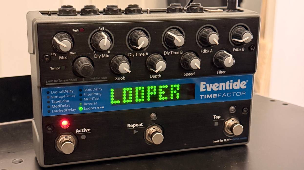
Recently a client brought me a very cool 2004 Fender Tele (Photo 1) that needed a new blade switch. His guitar played well (and looked great too) but the switch had started to cut out at random times onstage. It’s not uncommon for a Tele switch to wear out—especially if you use it vigorously—so let’s see what it takes to replace it.
We’ve previously covered how to install both 3-way Gibson and 5-way Strat switches, so this project will complete the set.
Plan of attack. I decided to install a CRL 3-way switch, a high-quality unit you can get from such luthier suppliers as Allparts and Stewart-MacDonald. (Oak Grigsby and Switchcraft are two other excellent brands.) Though they cost a few more bucks than cheapos, good switches will give you much longer service and are well worth the investment.
After gathering your tools and supplies (soldering iron, 60/40 solder, 12-gauge stranded wire, hemostats, and a medium-tip Phillips head screwdriver), unscrew the control plate, flip it over, and eyeball the existing 3-way switch. Remember to place the screws in a small box so you don’t lose them. Plus, you don’t want a wayward screw to end up under the guitar because it will scratch the finish.
Tip: Before you unsolder and remove the switch, draw a diagram of how it’s wired. Even if your new switch comes with a diagram, it’s a good idea to document where each wire is attached on the original one.
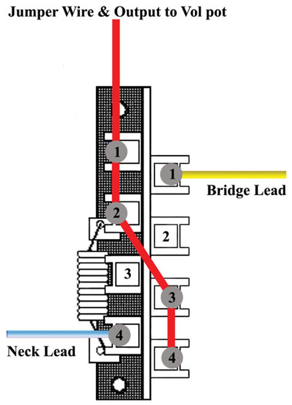
Fig. 1
The old switch in this guitar used the traditional Fender wiring, so my diagram looked like Fig. 1. This is the standard Tele configuration.
Fire up the iron. The next step is to unsolder the two pickup wires from the blade switch. On a stock Tele with single-coils, there should be one lead wire to remove for each pickup. When soldering or unsoldering a wire, grip it with a pair of hemostats so you won’t burn your fingers! Once the solder is molten, give the wire a gentle yank to pull it free.
In addition to the pickup leads, there’s one wire that connects the output of the switch to the input of the volume control. Unsolder this wire from the switch only. In all, there are three wires to unsolder from the switch.
Detach the old blade switch. Next remove the two mounting screws that fasten the original switch to the control plate. Typically these are Phillips head screws, but some guitars require a small flathead screwdriver. The blade switch should drop right out of the control plate.
If you have a guitar with an inexpensive “box” switch, confirm that the mounting holes line up properly for the new switch you intend to install. Some imported guitars have different hole spacing than U.S.-built models for mounting the switch onto the control plate. If that’s the case, you’ll either need to get a new box switch or swap out the old control plate for a new one with hole spacing that matches an American CRL switch.
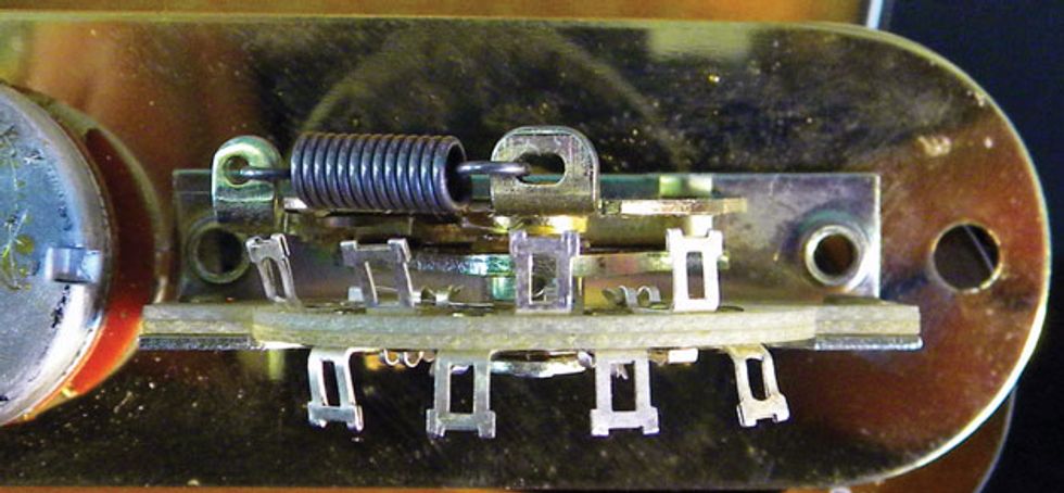
Photo 2
Photo 2 shows the CRL switch I’m about to install. Take a moment to compare it to the wiring diagram. Use the spring to orient yourself with the various lugs and their functions.
Install the replacement switch. CRL switches come with mounting screws, and you can either use them or the screws from the original switch, assuming they fit. Mount the switch on the control plate, then insert and tighten the screws.
Note: You can install the switch oriented in either direction, but sorting out the wiring will be easier if the new switch is oriented the same way as the original. In other words, if the spring on the old switch was facing the pickups, then mount the new switch that way too.
Wire up the new switch. There are four lugs for attaching wires on each side of the blade switch, making a total of eight lugs. For this classic Tele scheme, we only need to solder three wires onto six lugs. Each pickup lead will have its own dedicated lug. The other four lugs will be used to join both sides of the switch and connect the switch to the volume pot.
Before you begin wiring, review this simple breakdown of the switch while comparing it to the diagram. Each number represents a different lug on the switch. Next to the lug number is a description of the wire you’ll need to solder.
Spring side of the switch
1. Output wire to volume pot
2. Connects to prong #1 (switch output)
3. Unused
4. Lead from neck pickup
Non-Spring side of the switch
1. Lead from bridge pickup
2. Unused
3. Connects to prong #2 on the spring side of the switch to join both sides
4. Connects to prong #3 (non-spring side)
Tip: Unsure of your soldering skills? Check out “Soldering 101: A Step-by-Step Guide.”
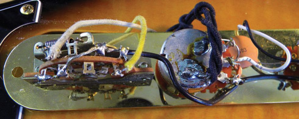
Photo 3
Solder the leads from the pickups to the blade switch, and then add a jumper wire to connect both sides of the switch to its output lug. For the jumper, use a piece of 12-gauge stranded wire. Be sure to “tin” the entire wire before you solder it onto the switch. Tinning the jumper will make it easier to solder the wire in place, and you won’t need much additional solder. Finally, solder the wire from the volume pot’s input lug to the output lug on the switch. Photo 3 shows the CRL switch with the completed wiring.
Test drive. Now it’s time to button up the Tele. Flip over the control plate and re-install the screws to secure it. (Aren’t you glad they’re in that little box?) Now you’re ready to test out your work. Your Tele should have the classic switching configurations:
• Position 1: Bridge pickup only
• Position 2: Bridge and neck pickups
• Position 3: Neck pickup only
If everything is working correctly, slap on a new set of strings to celebrate the completed project and get ready to enjoy your new switch!