Hello Jeff,
I have a Hiwatt DR-201 AP that makes the most glorious sound I’ve ever heard with a guitar. But it’s loud! I have a 200-watt Weber attenuator, but it can’t take the output. Can I pull power tubes from this amp to reduce the volume? If so, which ones? Is there a way to get the amp down to 50 watts?
Thank you!
C.J. Rebel
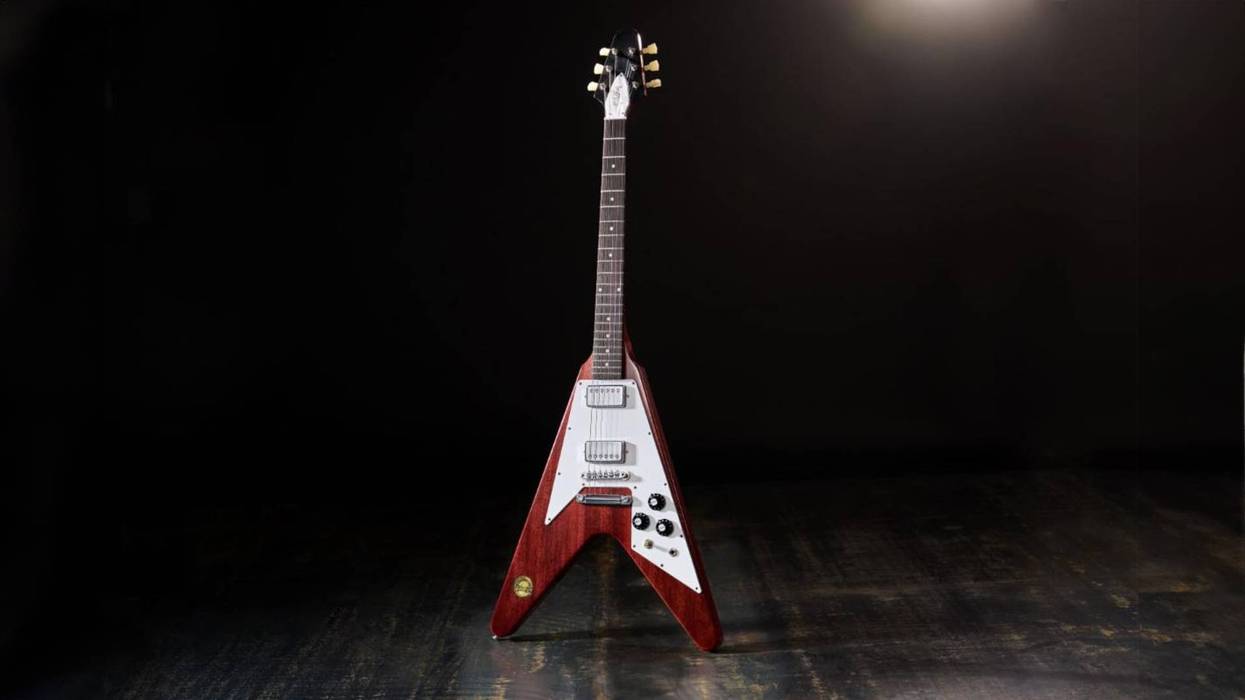
Thanks for your question, C.J. A Hiwatt DR-201 (Photo 1) is a rare creature, and it’s pretty evident why: Where can you unleash a 200-watt head these days? (We’ll leave those pesky bass players out of this.) Anyway, I completely understand what you mean by “the most glorious sound I’ve ever heard.” I’ve always compared playing a chord through a Hiwatt to hearing one on a grand piano. It’s a big, bold, full-frequency sound.
And the percussive factor of a 200-watt (or even larger) Hiwatt is damn near frightening, so I sympathize with your plight. As for your question about pulling tubes, in this particular case I would highly recommend against it. The power-supply voltages are already substantial (even dangerously high), and removing tubes would cause that voltage to rise even higher. So let’s see if we can achieve your goal in a different way.
According to schematics I’ve perused, Hiwatt apparently produced two versions of the DR-201: One with six EL34s in the output stage, the other powered by four KT88s. Theoretically, the four-KT88 model is more capable of producing the 200-watt stated output than the six-EL34 version, which would probably be closer to 150 watts.
But I don’t believe either configuration actually produces 200 watts of continuous power. The power supply design in both amps should be identical, and while the stated 650V DC plate voltage should be more than ample to support a 200-watt amp (given enough current capability), the power supply only provides 410 volts to the screen grids of the tubes.
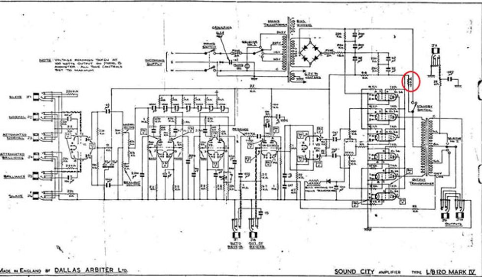
Image 1
This is atypical for a guitar amp, as usually the plate and screen grid voltages are almost identical. Think of the screen grid as a governor on an engine: A voltage close to the plate voltage creates almost no governing, while a markedly smaller voltage “throttles back” the amp’s output power. Lowering the voltage on the screen grids by increasing the size of the power-supply resistor that feeds them reduces the continuous output power of the amp. This modification can be used on similar amps with six EL34s in the output stage—for instance, a Sound City head.
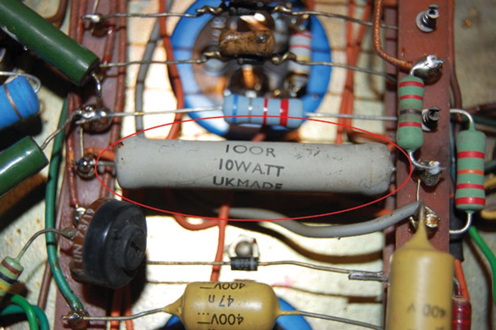
Photo 2
In the Sound City example, we can increase the value of the 100-ohm resistor (Image 1 and Photo 2) to 2000 ohms (2k), which reduces the output power to approximately 50-60 watts. But as mentioned before, this voltage is already substantially lower in the Hiwatt amp, which leads me to believe that it may actually fall short of 200 watts of continuous power.
However, that’s not to say it isn’t loud, as the high plate voltage would give the DR-201 great potential for peak power during the note attack—which we know it has! So we can’t perform that type of modification on your amp because it already exists, but there is one more modification that can tame the beast.
This next mod will lift the output tube cathodes from ground, thereby reducing the output power. Fender actually employed a very similar design in some of their post-CBS-era amps. Their new engineers were always trying to “improve” things, but I’m not quite sure what their goal was with this design, as it held back the amp’s clean output power. Fortunately that’s exactly what we want here, so let’s do it.
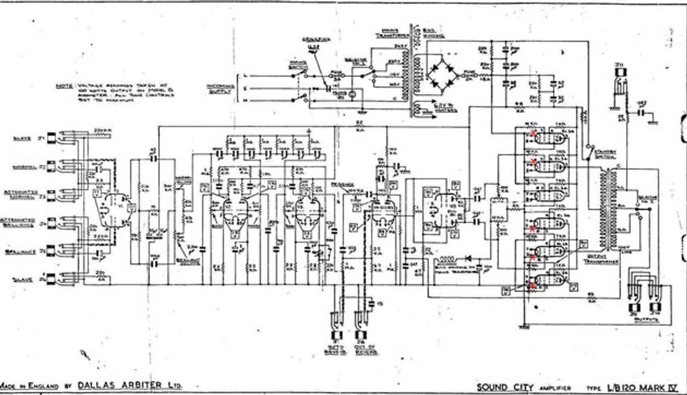
Image 2
As shown in Image 2, I did this modification to a Sound City amp, and it did indeed retain all its tonal characteristics while making the amp much more useable and more easily pushed into overdrive.
With the amp chassis upside down (of course) on the bench, locate the four (KT88) or six (EL34) output tube sockets. You should see pins 1 (to the right of the locating keyway) and 8 (to the left of the keyway) tied together and connected to ground. The ground connection will either be right at the tube socket, or made with a common wire connecting all the tubes to ground.
Disconnect pin 8 (left of the keyway) from this ground connection on all the tube sockets, while leaving pin 1. I recommend doing this with the output tubes removed because it makes for easier de-soldering and soldering, since the tube pins aren’t stealing all the heat from your soldering iron.
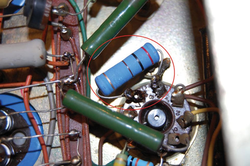
Photo 3
Next, install resistors from pin 8 to the ground connection, which should still be pin 1 (Photo 3). These resistors should be at least the 5-watt variety. A 100-ohm value should place the amp in the 100-watt range, while 200-ohm resistors will drop it to approximately 50-60 watts.
Well, there you have it. The amp is now quasi-cathode biased and should sound very cool and manageable.

![Rig Rundown: The Black Crowes’ Rich Robinson [2026]](https://www.premierguitar.com/media-library/youtube.jpg?id=66952027&width=1245&height=700&quality=70&coordinates=0%2C0%2C0%2C0)