Hi Jeff,
I recently acquired a 1972 Fender Vibro Champ, and after trolling the web discovered that there were actually two circuits used in the Vibro Champ: AA764 and AB764. I believe most people think that only the AA764 circuit was used in these amps, but from the schematic, it seems the AB764 circuit appeared around 03/24/71. The AB764 circuit contains changes to the (higher) voltages used in the amp, and also a cap can change from a 20-20-20 can to a 40-20-20 can. Do you know if all the 1972 and later Vibro Champs used the AB764 schematic? Is there any way to tell whether a Vibro Champ uses the AA or AB version of the circuit without opening it up?
Tom
Olathe, KS
Hi Tom,
I searched extensively but could not locate a schematic with the number AB764 specific to the Vibro Champ—all I found was the usual AA764. The other schematic you reference, AB764, was actually for the Bronco amp. The Bronco was essentially a Vibro Champ with a different name. The Bronco name appeared on the front panel in red rather than the usual blue, and the amp was packaged with the Bronco guitar as a beginner’s set sometime around 1967. That said, let’s see if there are any explanations for the differences between these schematics.
The schematic for the CBS-era Vibro Champ shows the main B+ voltage at the first power supply filter cap as 355V DC. This is supposedly achieved with a 5Y3 rectifier tube using a mains transformer with part number 125P1B. The plate voltage of the 6V6 output tube is stated as 342V DC, giving us a 13V drop across the output transformer primary, which is certainly possible.
The pre-CBS AA764 Champ schematic shows a 5Y3 and P1B mains transformer, with a B+ voltage of 360V DC and plate voltage of 350V DC—very similar to the CBS Vibro Champ.
Meanwhile the Bronco schematic shows the voltage at the first power supply filter cap as 420V DC. Keep in mind that this is supposedly while using the same 5Y3 rectifier and same 125P1B mains transformer as the CBS-era Vibro Champ, though if everything else in the amp is the same, this is theoretically impossible. Also, the stated plate voltage of 342V DC indicates a voltage drop of 78V across the primary of the output transformer. If that was truly the case in a (semi) functioning amplifier, my initial diagnosis would be a bad output transformer. Let’s just assume that someone forgot to update a few numbers here.
I’m not sure there’s a hard, factual explanation, though I do have a theory. To explain, let’s look at the era’s Princeton amp, which uses the same mains transformer as the era’s Champ and Vibro Champ. Perhaps the engineers at Fender decided at some point to design a double-duty transformer, one that could supply the needed voltage for a Champ with a 5Y3, but with sufficient current to supply a Princeton and the increased voltage output from its GZ34 rectifier.
The schematic and layout diagram hint at transformer redesign. Notice how in the Bronco schematic, there’s an internal “shield” lead added to the transformer. This is also indicated on the physical layout diagram for the Bronco by the addition of an orange lead to the mains transformer. So while the part number of the Champ and Vibro Champ transformer never changed, there may have been a redesign resulting in increased voltage.
This is pure conjecture, though the belief that there are Champ amps with different B+ voltages seems to be shared by some aftermarket transformer manufacturers, who offer replacement transformers with selectable secondary taps for higher or lower B+ voltages.
Can you tell which version you have without disassembling the unit? Maybe. The only externally visible clue may be the capacitor. If you can see the side of the large silver filter capacitor mounted on the underside of the chassis (this may require a flashlight and a mirror), you should be able to read the capacitance and voltage of each section written on the side. The first line will either say 20 µF or 40 µF (Fig. 1). If it’s 40, you might have the later, higher-voltage version, even though Princeton amps of the same era with the same mains transformer use a 20 µF cap in this position.
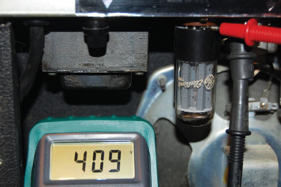
You’ll get a more definitive answer if you measure the voltage at pin 8 of the rectifier tube. Connect the negative lead of a voltmeter to a ground point. (Any point on the chassis will do.) Carefully pull the rectifier tube just slightly from its firmly seated position in the socket, just enough to let the voltmeter’s positive lead touch the pin (Fig. 2). Here you can measure the initial power supply voltage. In this instance, on a unit with the 40 µF cap, you can see I’ve measured 409V DC, which is neither the lower or higher power supply voltage stated on the schematics! Bottom line: It remains a mystery.
Warning:
All tube amplifiers contain lethal voltages. The most dangerous voltages are stored in electrolytic capacitors, even after the amp has been unplugged from the wall. Before you touch anything inside the amp chassis, it’s imperative that these capacitors are discharged. If you are unsure of this procedure, consult your local amp tech.
![Rig Rundown: The Black Crowes’ Rich Robinson [2026]](https://www.premierguitar.com/media-library/youtube.jpg?id=66952027&width=1245&height=700&quality=70&coordinates=0%2C0%2C0%2C0)