Let's continue our Telecaster adventure that began several columns ago (“Preparing Your Tele for Future Mods," June 2013, and “Fighting Feedback in a Telecaster," July 2013). We're laying the groundwork for a series of Tele mods, so it's important to have all the info at your fingertips. The next step involves an intense investigation into several factory-spec Telecaster wirings. First we'll see how they evolved and then we'll look at ways to mod them.
A while back, I showed you Leo Fender's two-pickup Esquire wiring, or Broadcaster blend circuit (“The Two-Pickup Esquire Wiring," April 2013), which was the first Telecaster wiring ever. In his original hand-drawn circuit, Leo identifies the 250k pots as “1/4 meg" and there's even a little error—the 15k Ω resistor is shown as “15M." You can see this drawing at the Fender Museum and it's one of the real treasures of the exhibit. For Tele freaks, it all started here.
This circuit was used for the two-pickup Esquire, which was later named Broadcaster. The guitar finally became the Telecaster in April 1951. This circuit is also the one you can find in all “Nocasters," so we can roughly say it was used from early fall 1950 to approximately May 1952. In literature, this span is often referred to as “from 1950-1953," which in most cases is precise enough.
Remember, the original two-pickup Esquire wiring is characterized by the absence of a real tone control. Instead, the second pot acted as a blend or pan control between the two pickups, and this was only engaged with the 3-way pickup selector switch in the rear position. In May 1952, Leo modified the circuit to incorporate a true tone control by skipping the blend functionality and discarding any two-pickup combination.
Today we know that it was not Leo's idea alone, and this change was mostly made because of Bill Carson's suggestions. Carson worked as a professional Western swing guitarist and was Leo's favorite guinea pig for testing his Telecaster and early tweed amp designs. Carson never really liked the blender wiring on his Telecaster and came up with the idea to incorporate a real tone control.
Viewing the 3-way switch from the playing position, here's how Telecaster circuit was modified. This is the switching matrix I'll use in all future Telecaster columns, so please keep it in mind:
Position #1 (switch lever on the right): Bridge pickup alone with tone control engaged. (This is identical to today's modern Telecaster wiring.)
Position #2 (switch lever in the middle): Neck pickup alone with tone control engaged. (On modern Telecasters, this position engages both pickups wired in parallel.)
Position #3 (switch lever on the left): Neck pickup alone with a bassy-sounding preset and no further tone control. (On a modern Telecaster, this selects the neck pickup alone with tone control engaged.)
This circuit is often referred to as the “dark circuit" or “blackguard" wiring and was roughly used from mid 1952 up to late 1967. Within this 15-year period, the circuit stayed mostly untouched, but Fender changed the specs of the two capacitors several times (more about this in a moment).
Electronically, the original dark circuit—often referred to as “dark circuit 1st generation"—features two 250k Stackpole audio pots, two Cornell Dubilier (CD) 0.05 µF/150V paper-waxed caps, and one 3-way pickup selector switch, originally from CRL with a 1452 imprint.
For all wire runs from the pickups and between the switch and pots, Fender used a waxed, cloth-covered wire in yellow, black, and white. Black was for all ground connections, white for the hot wire from the neck pickup, and yellow for the hot wire from the bridge pickup, as well as all connections between the switch and pots.
Fig. 1 shows the wiring scheme. Note: In this diagram, the colors differ from the original dark circuit I just described.
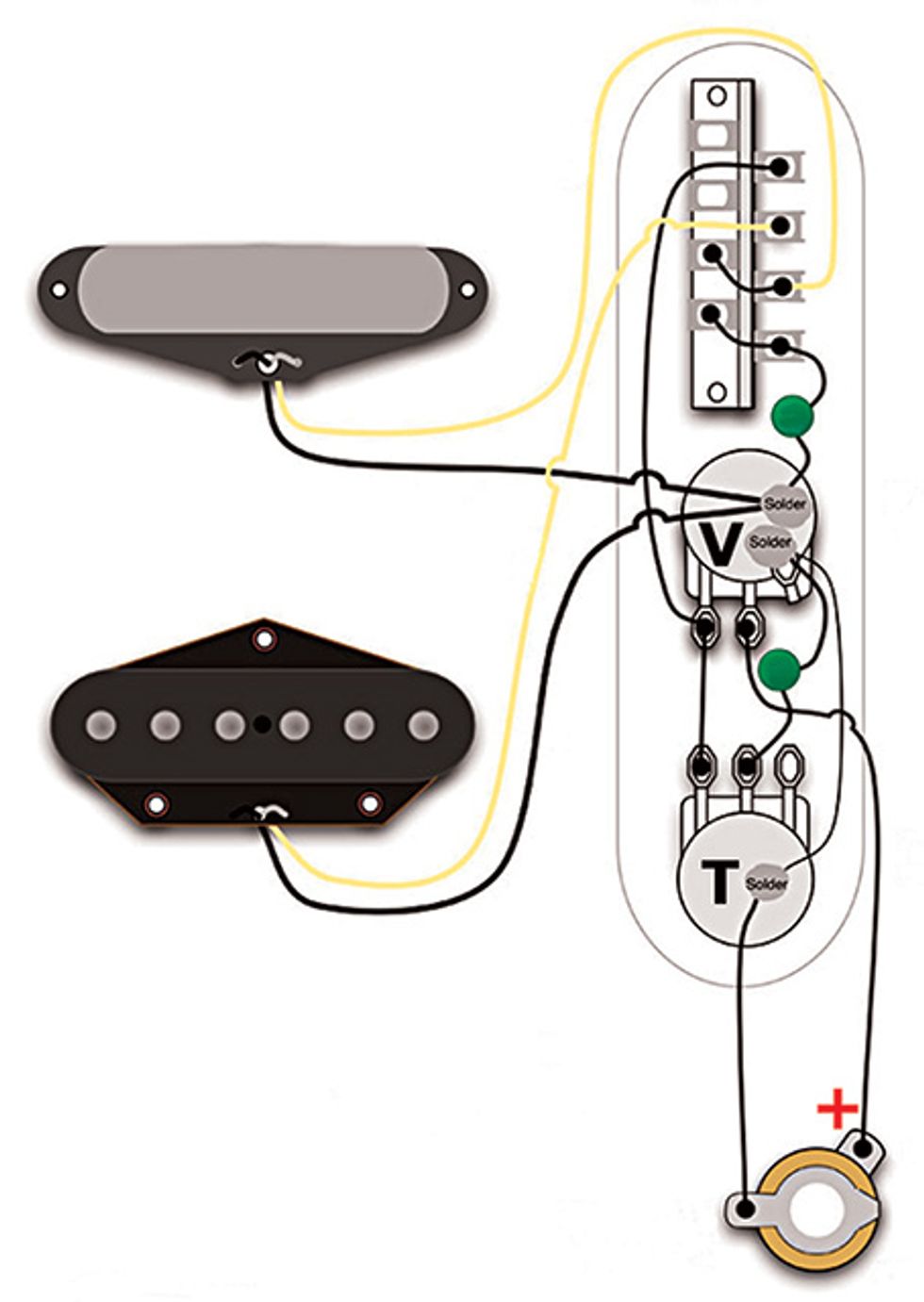
Diagram courtesy of Seymour Duncan.
Today's Tele players will be familiar with switching positions 1 and 2 (though on modern Teles, the neck pickup alone is in position #3, rather than #2), but position #3 with the bassy preset is something that's mostly forgotten today and worth a deeper look.
With the neck pickup alone and the 0.05 µF tone cap engaged, the sound is very dark—a preset “organ tone" that Leo Fender thought would inspire guitarists to play bass lines. Some contemporary jazz guitarists like this dark tone, but in the '50s guitarists didn't want to play bass lines. Leo believed in this feature, so he transferred it from the original two-pickup Esquire to the Tele, and it stayed untouched until late 1967. This was one of the very first things players started to modify in their Teles because it was unpopular right from the start.
Here's how the “dark circuit" evolved over the years: The pots' resistance didn't change until 1969, staying at 250k audio, but depending on availability, Fender used different brands, such as Stackpole, Centralab, and CTS. In late 1952, the value of the cap between the 3-way switch and the volume pot changed from the original 0.05 µF to 0.1 µF, making the preset bassy sound even more bassy. This is referred to as “dark circuit 2nd generation." The cap between the volume and the tone pot (this is the real tone cap) always stayed 0.05 µF.
Fender used paper-waxed caps from Cornell Dubilier until 1961, always with a 150V rating. The tone cap between the two pots retained its tubular shape, but the original 0.05 µF tubular-shaped cap between the volume pot and the 3-way switch became a chiclet shape when it changed to the 0.1 µF capacitance in late 1952.
In 1961, Fender replaced the paper-waxed caps with 50V ceramic caps. These are often referred to as “red dime" and “orange dime" (or “circle D") caps.
It's possible to be more precise in describing capacitor changes, but I don't want to make this a collector's bible or reference. The tonal differences between paper-waxed and ceramic caps are much more significant than all the little changes during the era of CD paper-waxed caps.
Next month we'll continue exploring the evolution of factory Telecaster circuits, so stay tuned. Until then, keep on modding!

Dirk Wacker lives in
Germany and is fascinated
by anything related to old
Fender guitars and amps.
He plays country, rockabilly,
and surf music in two
bands, works regularly as a
session musician for a local studio, and writes
for several guitar mags. He's also a hardcore
guitar and amp DIY-er who runs an extensive
website—singlecoil.com—on the subject.

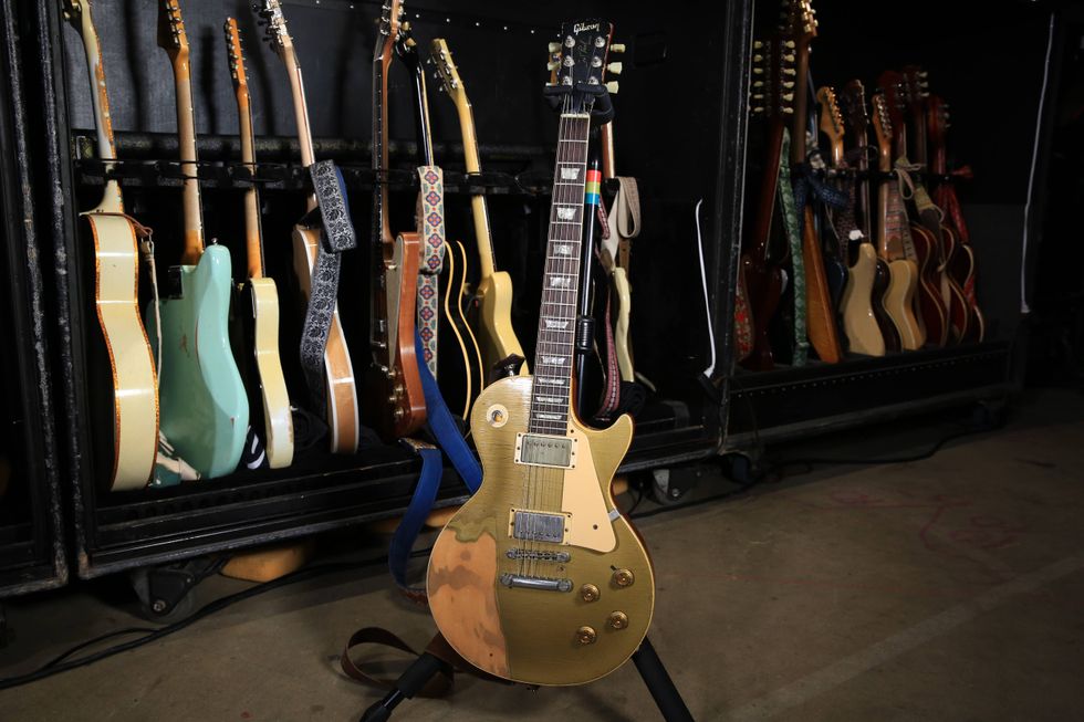
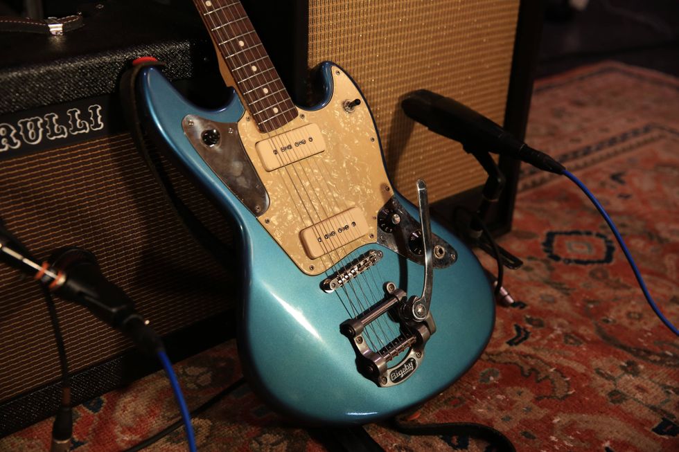
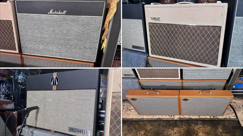
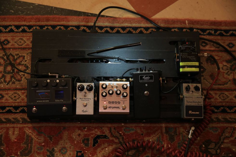
![Rig Rundown: The Black Crowes’ Rich Robinson [2026]](https://www.premierguitar.com/media-library/youtube.jpg?id=66952027&width=1245&height=700&quality=70&coordinates=0%2C0%2C0%2C0)