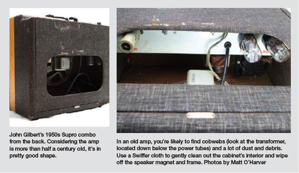
In last month’s column, John
Gilbert wrote in to ask about
restoring his mid- to late-1950s
Supro combo amplifier, and I
began describing different steps
he could take to get the amp up
and running. We discussed retubing,
and also replacing the line
cord and grounding capacitor. If
you missed that column or just
want to refresh your memory,
visit premierguitar.com/jan2011
and give it a quick read (the photos
are pretty cool, too). Now let’s
continue with the overhaul, picking
up where we left off.
John, once you’ve added a grounded plug as I outlined last month, a good electrical cleaning comes next. Spray each tube socket one at a time with an electronic contact cleaner that does not contain any lubricant, and then repeatedly cycle the tube in and out of its socket (6-10 insertions and removals are usually sufficient).
Once that’s done, use a similar method to clean the input jacks, but this time use an electronic contact cleaner that does contain lubricant. Again, move the plug in and out of the jack to get rid of any corrosion or dirt.
Now, if there are any openings on the body of the front-panel potentiometers, spray the lubricant cleaner inside the pot and rotate the control numerous times. This is a good time to make sure all the jacks, nuts, and screws are tight. Tight hardware assures the safest and quietest operation.
Filter capacitors are another item to address. Most often, I make the decision whether or not to replace an amp’s filter caps based on the condition of the caps, how the amp sounds, how the amp looks on the bench test gear (various meters and scopes), and whether a customer is concerned about maintaining as much originality as possible.
Because I can’t physically see your Supro or play through it, and your intention is to make it a reliable and safe practice amp, I’d recommend replacing these capacitors. These will be the largest capacitors inside the amp, so they shouldn’t be too hard to find. According to the schematics, the amp should have either three 10 μF 450V or two 10 μF 450V and one 40 μF 450V caps. If these are all discrete components, then any currently available electrolytic filter capacitor will yield more than adequate results for this project. If these are multi-section caps (that is, with more than one capacitor inside the enclosure), then Antique Electronic Supply (tubesandmore. com) will probably be the place to source these.
Incidentally, if you need multi-section caps but can’t seem to find any to purchase, you can also use individual capacitors in place of the multi cap. Connect the positive end of each cap to the appropriate positive connection of the original capacitor, and remember to connect all the negative connections to the same place that the original capacitor’s negative was connected.
Once you’ve done all this, you should be ready to reassemble and check out the amp. If the amp powers up, has a decent output, and is relatively noise free, then I believe a declaration of “job well done” is in order.
If the amp fires up but emits background noise—such as lowlevel popping or a sound like a crackling bowl of Rice Krispies— I’d suggest replacing the 6SL7 preamp tube (if you haven’t already). If the noises still persist with a new tube, it’s time to start replacing some of the only remaining components in this basic amp.
I’d first concentrate on the preamp-tube plate resistors. These resistors might have a value of 100k (brown-blackyellow) or 220k (red-red-yellow) or 270k (red-violet-yellow). Replacing them with any carbon- film or carbon-composition resistor will be fine. I prefer to use 1-watt resistors in tube amps, but traditional 1/2-watt types will work, if necessary.
While replacing these resistors, I’d also suggest replacing the associated signal caps. When working on significantly old equipment, it’s a good idea to minimize the number of times you remove and reattach components on the terminals of the aging tube sockets. Since this is not a “keep everything original” project, let’s do it all at once.
Reviewing the schematics, I see these caps consistently seem to be labeled 0.05 μF. Since a 0.05 μF cap is not a readily available value, feel free to substitute any quality 0.047 μF 600-630V DC capacitor. Again, a Sprague Orange Drop or similar poly-cap will work fine.
If the amp still sounds like breakfast, I’d replace the preamp-tube cathode resistors. These may be older values, such as 2k (red-black-red), which are not as readily available, but it would be fine to substitute a 2.2k or 1.8k in these instances. Again, if there are cathode bypass capacitors associated with these resistors, I suggest replacing them at the same time. They will more than likely be of the 25 μF 25V variety, and any currently available 22 μF or 25 μF 25V cap will suffice.
Well, if you’ve come this far, you have an almost completely rebuilt Supro—and you’ve been a willing participant in the process, not just a spectator. That can yield a lot of satisfaction, so enjoy!
 Jeff Bober is one of
the godfathers of the
low-wattage amp revolution,
co-founded and was
the principal designer for
Budda Amplification. Jeff recently launched EAST
Amplification, and he can be reached at
pgampman@gmail.com.
Jeff Bober is one of
the godfathers of the
low-wattage amp revolution,
co-founded and was
the principal designer for
Budda Amplification. Jeff recently launched EAST
Amplification, and he can be reached at
pgampman@gmail.com.