Put your hand in front of an empty electric socket, and you won't get a shock— because electrons just don't fly through space, right? Well … they will under the right conditions—like inside a vacuum tube.
Here we're going to take a look at the inner workings of standard amplifier circuits—the tubes, transformers, resistors, and capacitors that work together to create the amazing tones that have powered countless songs for the past 60+ years. While this stuff may be daunting to some of you, take heart—this is century-old technology. The basic concepts really are not too difficult to grasp.
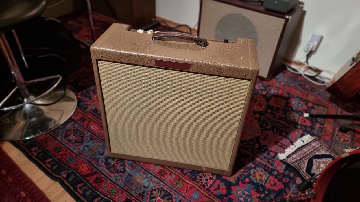
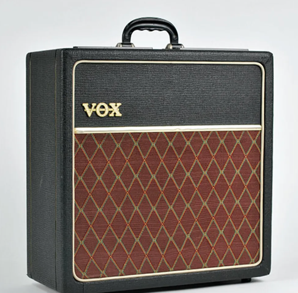
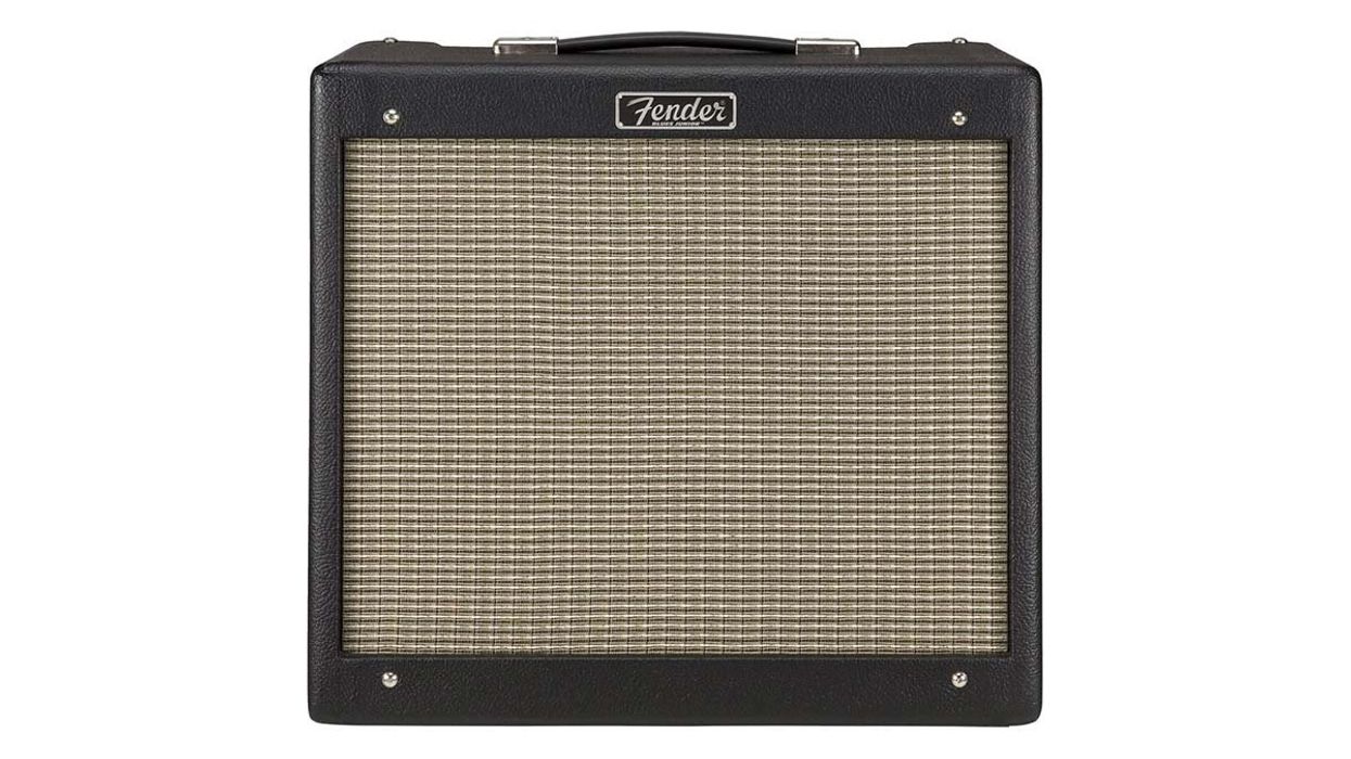
We'll discuss amplifier circuits by looking at my absolute favorite small amp, a 1960s Vox AC4. While it's small and simple, an AC4 actually is not the simplest guitar amp out there. Unlike Fender's earliest tweed Champs, the AC4 has a tone control and tremolo, which gives us a bit more to talk about.
But before we get started, let's make it clear that this article is not in any way encouraging or equipping you to open up the back of your amp and start poking around. Make no mistake: Amplifier circuits, even when unplugged, contain voltages that can kill you. And if you're an amp tech, please excuse any oversimplification in the discussion—this is a primer for general consumption, not a compendium of possible exceptions and anomalous phenomena.
The Vacuum Tube
First, let's talk about some basic principles of electricity. An electron—the heartbeat of electric energy—is a negatively charged subatomic particle. In a vacuum (i.e., in the absence of air and matter), an electron will, in fact, fly through space if attracted by a sufficient positive charge—because opposites attract. Experiments conducted well over a century ago demonstrated that electrons will not only fly through space, but they can also be controlled. Scientists showed that, in a vacuum, electrons flowing from a heated metal element—the cathode—and being pulled toward a positively charged element—the anode—can be deflected by a magnetic field.
Cathode vs. Fixed Bias
A Vox AC4, like many amps, is designed to make the power tube's cathode slightly positive—a state that is commonly referred to in the guitar universe as cathode biased. Other amps, instead, put a negative charge on the power tube's grid. That's called fixed bias, and it has a similar effect. Either method causes electrons to stay put on the cathode until needed.
Learn how to control that magnetic field accurately and, as RCA did, you can display an image of Felix the Cat on a phosphorescent surface at the far end of the tube. The tube used in that case was the cathode ray tube (aka CRT)—better known today as an old, pre-LCD/LED/plasma television.
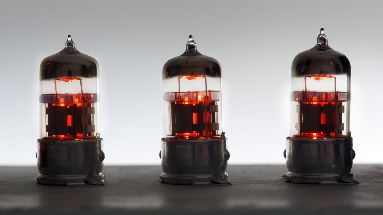
In guitar amps, we're not that interested in displaying images with our tubes, but we're still very interested in controlling those electrons—and we can use a guitar to do it. Picture this: In the center of a tube's glass envelope is a cathode. It carries just a slight positive charge, and it's ready to release a gazillion electrons. It's especially ready if it's been heated. Surrounding the cathode is the anode—although in the guitar universe we typically call it the plate. The plate carries a high positive charge that's ready to pull those negative electrons toward it. To the highly positive plate, the cathode's slight positive charge still makes the cathode seem negative (we'll talk more about this slight positive charge later). If you place these two elements in a vacuum and power them up, electrons will fly relentlessly toward the plate. When you add a third element—the grid—between the two, you can control the flow of electrons. And when you position the grid close to the cathode and connect the grid to the relatively tiny voltages coming from your guitar pickups, something interesting happens: The tiny signal unleashes a flood of electrons, allowing them to fly freely to the plate. That rush of electrons from the cathode to the plate mirrors the signal from the guitar, amplifying its signal many times over.
Okay, so let's get back to that earlier mention of the slight positive charge. The reason we want the cathode to carry a slight positive charge is that it makes the grid, with no charge yet applied, seem negative. Voltages are relative. And while opposites attract, like charges repel. The apparently negative grid close to the cathode will keep those negatively charged electrons in place until the guitar signal is ready to swing the grid positive to release them.
One other useful electron-related fact to know is the difference between voltage and current. Think of current as the amount of water flowing through a pipe. More current means more water being delivered. Voltage, on the other hand, is like water pressure— it's the force behind that water. Increase the voltage (pressure) and you'll increase the current (amount of flow). A resistor acts like a constriction in the pipe, with more resistance being analogous to a tighter constriction. So it follows that placing a different resistor in a circuit will affect both the voltage and the current.
What actually goes on inside a guitar amplifier is obviously a bit more complex than just the flow of electrons in tubes, though. Next we'll do a quick overview of the additional parts involved, followed by more detailed, part-by-part descriptions.
The Voltages
The first and largest component in an amp circuit, aside from the speaker, is the power transformer. It supplies electricity to the circuit, converting AC voltage from the wall to proper AC voltages for the amp. AC (aka alternating current) is a sine wave of electricity—an alternating positive and negative voltage coming from our electric sockets at 120 volts, 60 sine waves a second in the U.S. (These operating voltages vary around the world. Standard voltage can be 100, 120, or 230 volts, at 50 or 60 cycles per second.)
AC4 Tubes
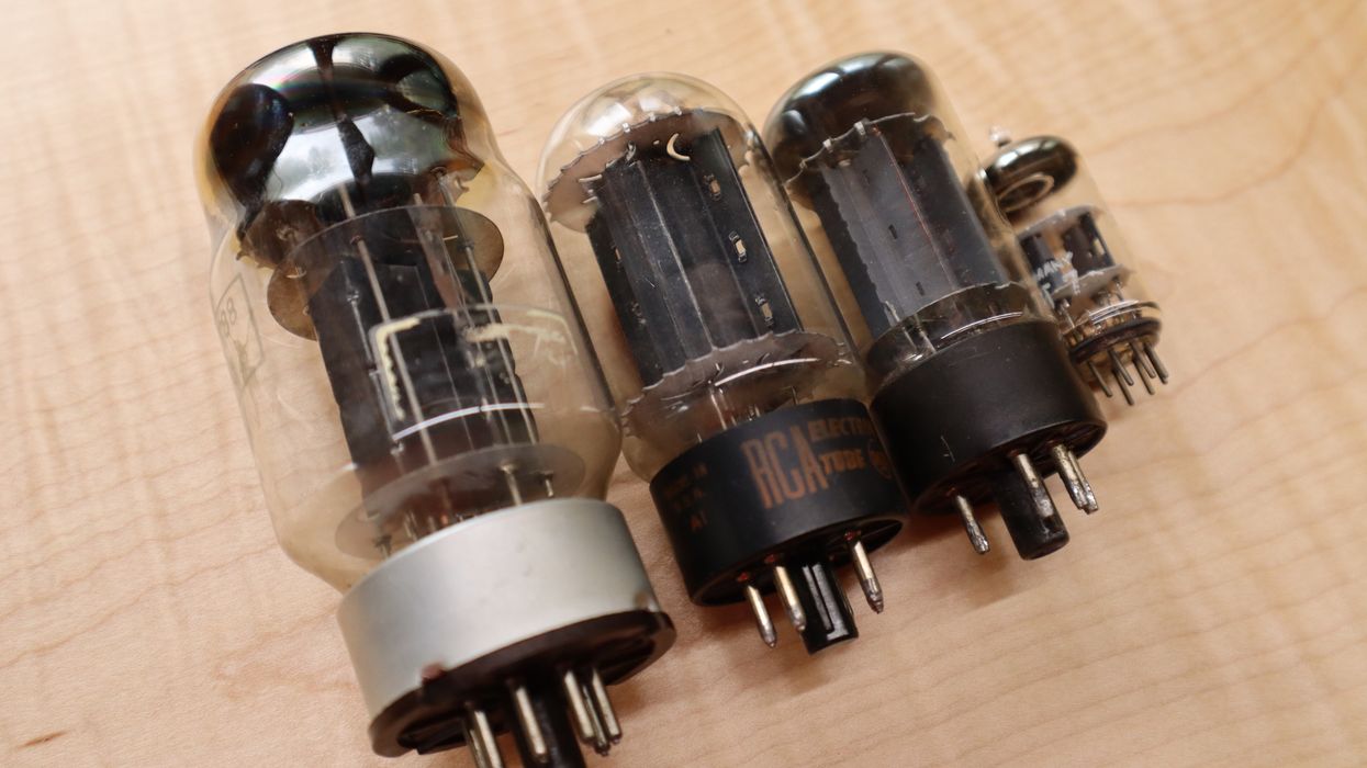
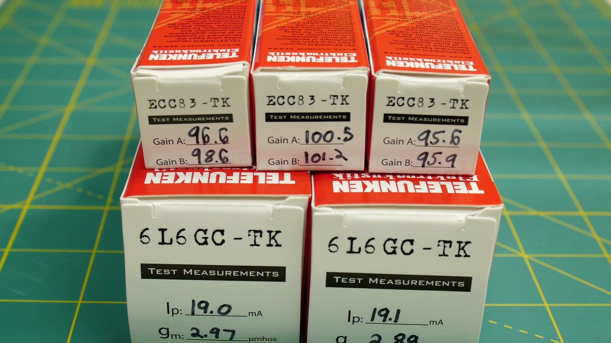
The AC4 uses four tubes—an EZ80 rectifier, an EF86 preamp tube, an EL84 power tube, and an ECC83 (12AX7)—to drive the tremolo circuit (which Vox calls a "vibrato" circuit.) The AC4 is designed to provide the plates of the latter three tubes with a different DC voltage that's appropriate for that tube.
The AC4's power transformer elevates the 120 AC volts to 250 volts AC, and then sends that voltage on to the rectifier tube, the first tube in the circuit. The rectifier tube's job is to convert AC voltage to DC (aka direct current—a steady positive voltage rather than a sine wave). The power transformer's other job is to supply low AC voltage to the filaments (the heaters) inside every tube in the amp—that's what gets the cathodes hot. The filaments in the AC4's tubes all work off of 6.3 volts.
Converting the power transformer's AC voltage to DC voltage coming from it isn't steady, it's more of a ripple. Filter capacitors—the large, cylindrically shaped components that come next in the circuit—help smooth out the ripples in the DC voltage. Filter capacitors are similar in construction to batteries in that they store a charge—a potentially lethal charge—even after the amp is unplugged. This is why you should never poke around inside an amp unless you've been trained to safely discharge the caps.
The high and relatively steady DC voltage dispensed by filter capacitors goes to the tube plates—the elements that need that high, positive, electron-attracting charge. The amount of voltage on a tube's plate is determined by the voltage coming off the filter caps, and also by resistors positioned along the DC line. With a high DC voltage, the plates are ready to start pulling electrons.
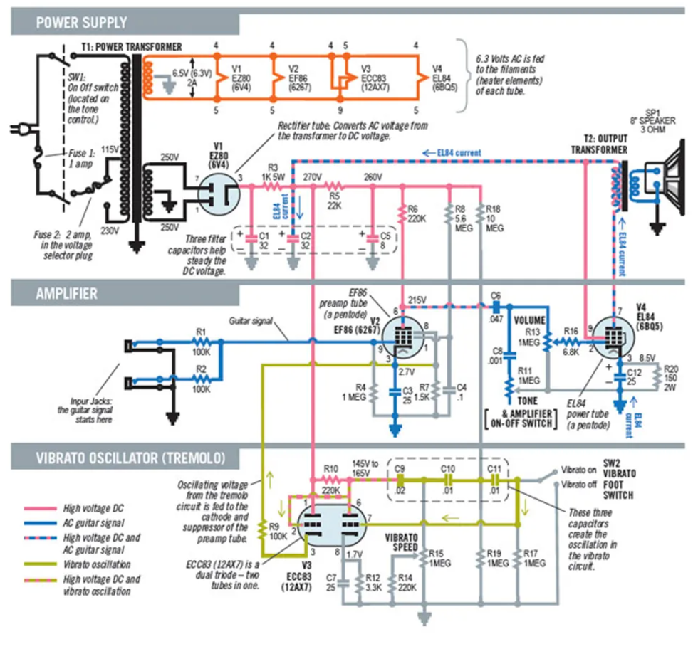
To the uninitiated, circuit schematics can look like a rat's nest of wires and components arranged in a way that saves space on paper—but that also needs to be mentally untangled in order to truly understand the circuit. Here is a 1960s Vox AC4 schematic, rearranged and color-coded to help you decipher what's going on. The original Vox numbering system for the resistors and capacitors (R1, R2, C1, C2, etc.) is included, in case you want to follow along using the original Vox schematic.
Note: AC and DC voltages can coexist on the same wire. In a guitar amp, the AC guitar signal is imposed on top of the high DC voltages. Fortunately, that AC signal can be separated: Capacitors in the circuit block DC voltages but allow the AC guitar signal to get through.
The Guitar Signal
We all know your guitar's signal comes from your pickups, but to understand the amplified signal, let's start at electrical ground. In practice, ground in a guitar amp means a connection to the chassis. (In the AC4 schematic, the ground connections look like upside-down Christmas trees.) Electrons flowing through a tube originate from ground. The cathodes of the EF86 and the EL84 each have a resistor attached to ground. This creates the small DC voltage on their cathodes to prevent the electrons from flowing. When the guitar signal reaches the grid, the electrons then flow. However, the cathode resistor alone would also affect electron flow when the guitar is played. A bypass capacitor is put in parallel with the resistor to increase gain and allow AC electrons to effortlessly get through. The electrons released by the guitar signal flow from ground to the EL86 cathode, then to the plate, through a .047μF signal capacitor, and through the volume potentiometer to the grid of the EL84. At the EL84, a similar electron flow takes place, but this time it's more powerful. Enough electrons will travel from the EL84's plate to the output transformer to drive the speaker.
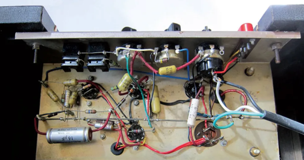
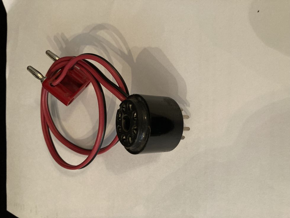
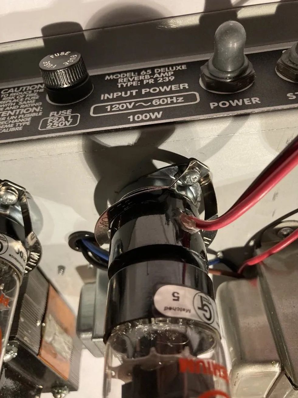
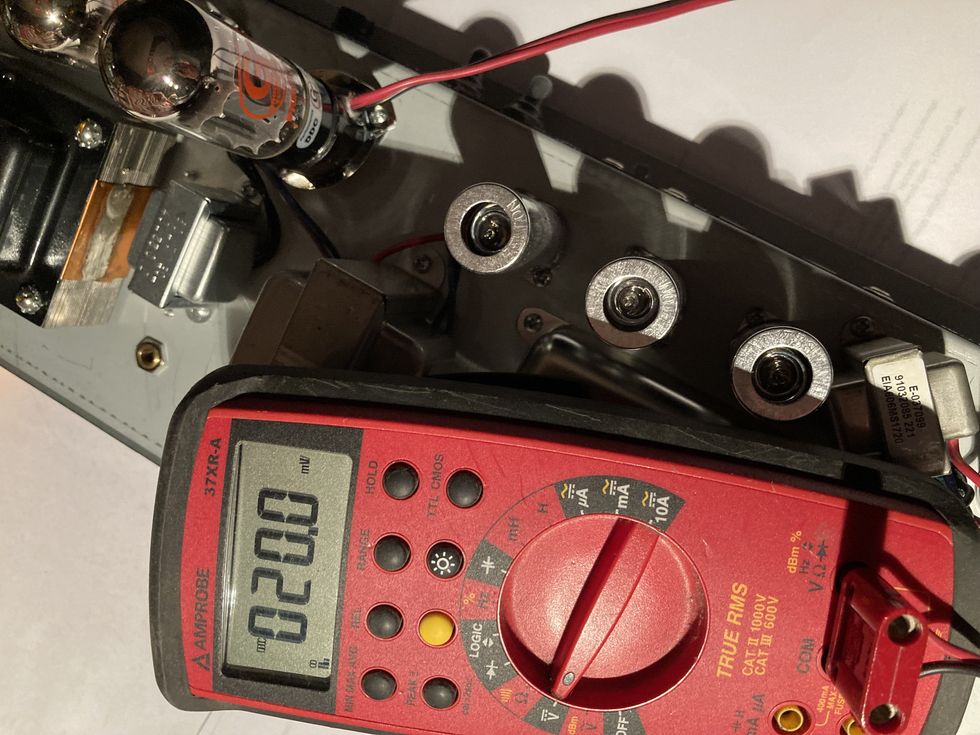
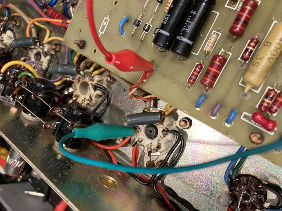
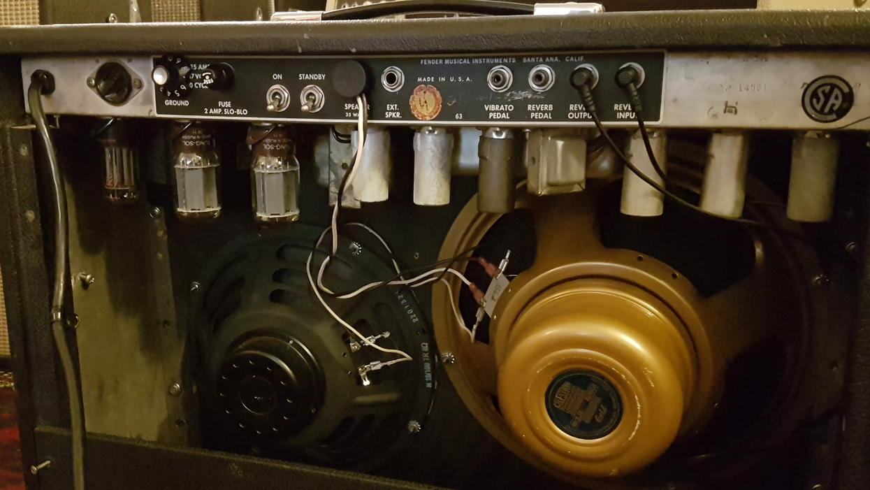
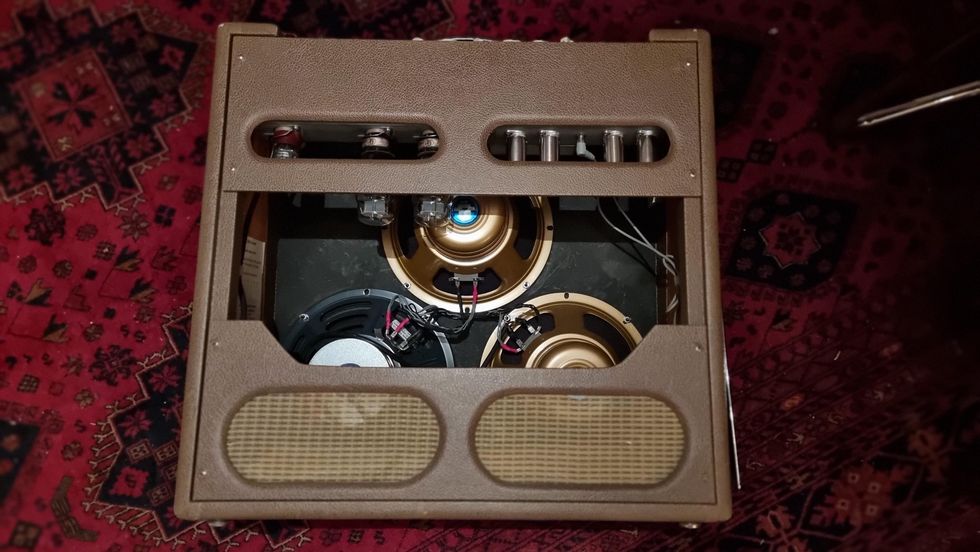
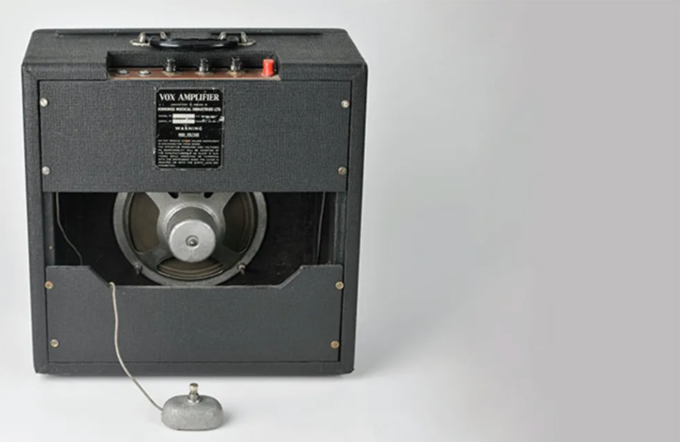
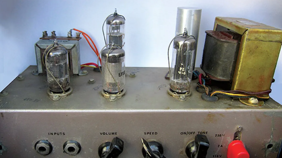
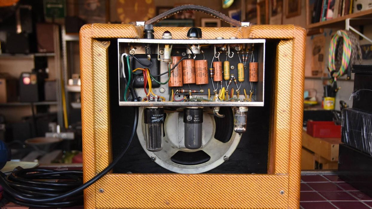
Here we see a view of the AC4's chassis with the back panel removed (above), and with the chassis removed from the amp (below)—a design that makes it a bit of a chore to try out tubes from various manufacturers, both old and new stock.
The electrons don't stop at the output transformer, though. If you look at the schematic, you'll note that they pass through it and cycle back to ground. In a way, you can think of an amplifier as an electron circulator whose ultimate goal is to send electrons through the output transformer. Our job as guitarists is simply to get those electrons to do that in tune and with reasonable timing.
The “Vibrato Oscillator" Circuit
You're probably familiar with the mix up in terminology between "vibrato" and "tremolo." The 1960s Vox AC4 schematic used "vibrato" to refer to the oscillation in volume that is more commonly referred to as "tremolo." Because some of you may want to refer to the original AC4 schematic, we'll stick with the company's terminology here.
The AC4's ECC83 (12AX7) vibrato tube creates a low-frequency oscillation. That oscillating voltage is connected to the cathode of the EF86 tube, which affects the bias. Think of it as sending a very low-sound signal to the EF86's cathode—maybe 2–10 Hz (cycles per second). These frequencies are way too low for the human ear to detect, but they do affect electron flow in the EF86 from 2 to 10 times per second.
Components in More Detail
Now that we've got our quick overview of how an amp works out of the way, let's get into some more detailed descriptions, component by component.
Power transformer
The power transformer is the amp's larger transformer. It converts 120V wall voltage (240V in many countries) to a high AC voltage entering the rectifier (EZ80 in the case of the Vox AC4) tube. The transformer also supplies 6.3V AC to the filaments (heating elements) of the tubes. (Some rectifier tubes require 5V for the filaments, but not the AC4's EZ80 tube.)
Capacitors (aka caps)
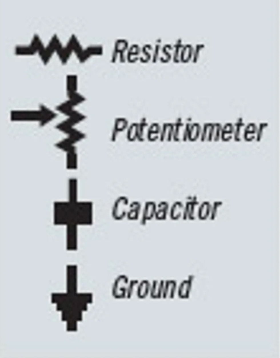
Capacitors are shown in the schematic as two parallel lines perpendicular to the wiring. In some schematics, one of the lines may be curved. There are three types of capacitors in a guitar amp—filter, bypass, and signal—and their values are measured in microfarads, which are designated by the symbol μF.
Filter capacitors are large metal cylinders that, like batteries, hold a charge—even long after the amp has been unplugged. Unlike batteries for household items like flashlights and smoke detectors, they hold potentially lethal voltages. These are why you don't mess around inside your amp unless you know how to do so safely. The rectifier tube's purpose is to convert the AC voltage (a sine wave) into a constant DC voltage to power the tubes. The rectifier tube does a good but not perfect job. What emerges is actually a ripple-like DC voltage, so the filter capacitors help reduce the ripple by storing and releasing high voltages. Filter caps typically have values in the range of 8–50 μF, sometimes higher. The AC4 uses two 32 μF caps and one 8 μF cap. The two 32s are actually both inside one cylinder—i.e., they are a single component in the amp. The 8 μF cap is a separate component.
As previously mentioned, in an AC4 a resistor and a bypass capacitor are connected to the cathodes of the preamp tube and the power tube, wired in parallel—meaning, side-by-side. (In the AC4 schematic, the cathode is the lower element in the tube diagram.) Current flowing through a resistor causes a change in voltage. Cathode resistors are used to add DC voltage to the cathodes (2.7V for the EF86 and 8.5V for the EL84). The purpose is to make the cathode positive in relation to the grid. That cathode resistor, however, also resists the guitar signal's current flow. Hence, the parallel addition of a bypass capacitor. Since a capacitor will block DC but allow AC to freely pass through, the bypass cap does what its name implies—it allows the electrons needed for amplifying the guitar signal to bypass the resistor and flow freely through the cathode. In an AC4, the EF86 and EL84 bypass capacitors are both 25 μF. Larger values would let more bass through, while smaller values would reduce it.
Signal capacitors, meanwhile, are the small caps inside the amp, and they perform two critical functions. First, they block DC voltage while allowing AC voltages (like the guitar signal) to pass through. They also determine, according to their value, which guitar frequencies will pass through. In other words, signal caps define the tone of the amp. AC4 signal-cap values range from .1 μF–.001 μF. Smaller values (like the .001 μF cap on the AC4's tone control) allow only treble frequencies to pass through. Put another way, the tone control sends high frequencies to ground instead of letting them reach the power tube.
Resistors
These are the small, cylindrical components with color-coded stripes indicating their value. If you haven't already guessed by their name, they resist the flow of electricity. They are represented in the schematic as a peaks-and-valleys shape, like a seismograph reading or a few capital V's strung together. Higher values resist the flow more than lower values. In doing so, they decrease voltage as electrons try to travel through.
Resistance is measured in ohms, often using the symbol Ω. A "k" after a number indicates thousands (i.e., 220k Ω = 220,000 Ω). "M" or "meg" indicates millions. The lowest value seen in an AC4 is 150 Ω, while the highest is 10M Ω (10 million ohms). In addition to ohms, resistors have a wattage rating. Most resistors in amps are rated at 1/2 watt. Wattage needs to be higher if the resistor is in the power section. In an AC4, the 1k Ω resistor located between the first two filter caps is rated at 5 watts. (Note: some amps will use a component called a "choke" here rather than a resistor. A choke is an inductor that looks like a small transformer. Inductors don't like changes in current flow, which means they will help choke out some of the ripple we spoke about, reducing amp hum.)
Preamp Tubes
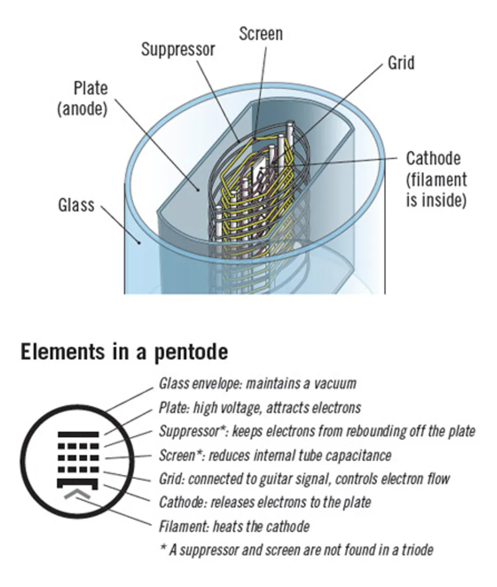
The first tube that your guitar pickups' signal will get to is the first preamp tube. In many amps, it's a 12AX7 (ECC83 in Brit parlance), but in the Vox AC4 it's an EF86. Remember the three elements inside a tube—the cathode, plate, and grid? The presence of those three elements define the tube as a triode tube. An EF86 adds two more elements, making it a pentode (from the Greek term "penta," meaning "five").
The two additional elements within a pentode are the screen and the suppressor. Like the grid, the screen and suppressor are wire wraps inside the tube, not continuous metal. This allows them to impose charges that affect the electrons while still allowing the majority of electrons to pass through. The presence of the cathode and plate within the tube makes the tube itself something of a capacitor. To reduce that unwanted capacitance, the screen is placed between the cathode and the plate, with a DC voltage applied. The suppressor is the wire wrap closest to the plate, and it is connected to the cathode. (In an EL84, this connection is made within the base of the tube.) Because the suppressor has large gaps in it, it has virtually no effect on electron flow from the cathode. Still, some electrons will hit the plate and bounce off. The suppressor sends the electrons from these "secondary emissions" back to the plate.
Power Tubes
Just as the guitar signal is amplified by the preamp tube, the signal from the preamp tube is amplified by the power tube. In an AC4, it's an EL84. The five elements in this pentode tube perform the same functions as the triode EF86's elements, only with greater current passing through.
Vibrato Oscillator
Besides preamp and power tubes, you'll see another tube in our AC4 and most other amps with a tremolo and/or reverb circuit. Often, as is the case with the AC4, it's a 12AX7 (ECC83).
Looking at the schematic, you'll notice something different about the 12AX7 relative to the EF86. It's a dual triode, meaning it has two separate triodes in a single tube. As used in the AC4 vibrato circuit, the two halves work closely together.
Unlike some other amps' tremolo circuits, which let you control the speed and intensity of the effect, the AC4's only offers a knob to govern speed. When the AC4's footswitch is open (i.e., when its internal contacts don't make a connection), the vibrato circuit is heard. It sends a voltage to the cathode of the EF86 preamp tube in pulses, while an array of capacitors and resistors along with the speed control determine the rate. Closing the footswitch sends the oscillation to ground, deactivating the vibrato effect.
The two halves of the 12AX7 are wired to invert the AC sine wave. Electron flow in the two halves works 180 degrees apart— completely opposite. There are three signal capacitors in the vibrato circuit, and each one offsets the sine wave 60 degrees. The vibrato speed control affects that offset. As mentioned, think of the vibrato circuit as outputting a low-frequency oscillation, 2–10 cycles per second—too low to hear as a sound, but affecting the EF86's cathode bias that many times a second.
If you look at the schematic, you'll see that the oscillation originates on the right side of the 12AX7, sending it to the grid on the left side. The cathode (pin 3) sends the oscillating voltage to the EF86. The result is a variation in the preamp tube's ability to allow electrons to flow, 2 to10 times per second.
Output Transformer
It may seem strange, but an amp's output transformer doesn't just provide power in any old way— it's critical to shaping the amp's sound. It does something interesting. Electrons flow through the power tubes' plates at high voltages but low current. The output transformer converts that to a low-voltage, highcurrent signal that will drive the speaker.
The high DC voltage on the tube side of the output transformer will not pass to the speaker side—the output transformer blocks DC. But it will transfer the AC guitar signal to the speaker side.
Output transformers are rated in impedance (i.e., in ohms) on the tube side, and resistance (in ohms matching the speaker) and watts on the speaker side. Impedance for an EL84 is approximately 5K Ω. The AC4's 8"speaker is rated at 3.2 Ω (basically 4 Ω). A single EL84 puts out 4 to 5 watts, so the speaker needs to be able to handle that (it shouldn't be a problem for most speakers—that wattage is pretty low).
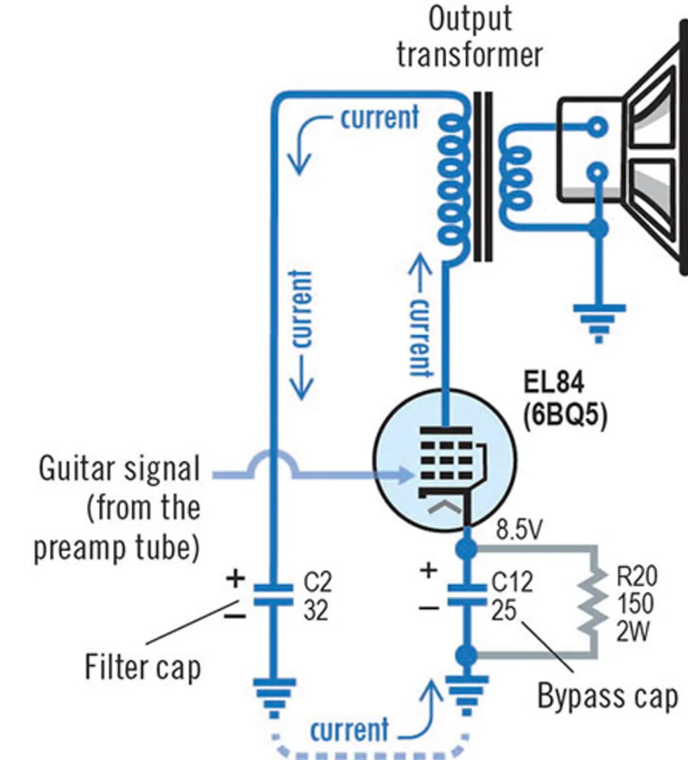
The ground connection plays a big role in understanding the flow of electrons through the power tube and to the output transformer. This simplified schematic shows the basic circuit. The amplified guitar signal pulls electrons from ground, through the bypass capacitor to the EL84 tube, through the output transformer, and through the filter capacitor back to ground.
Class-A Operation
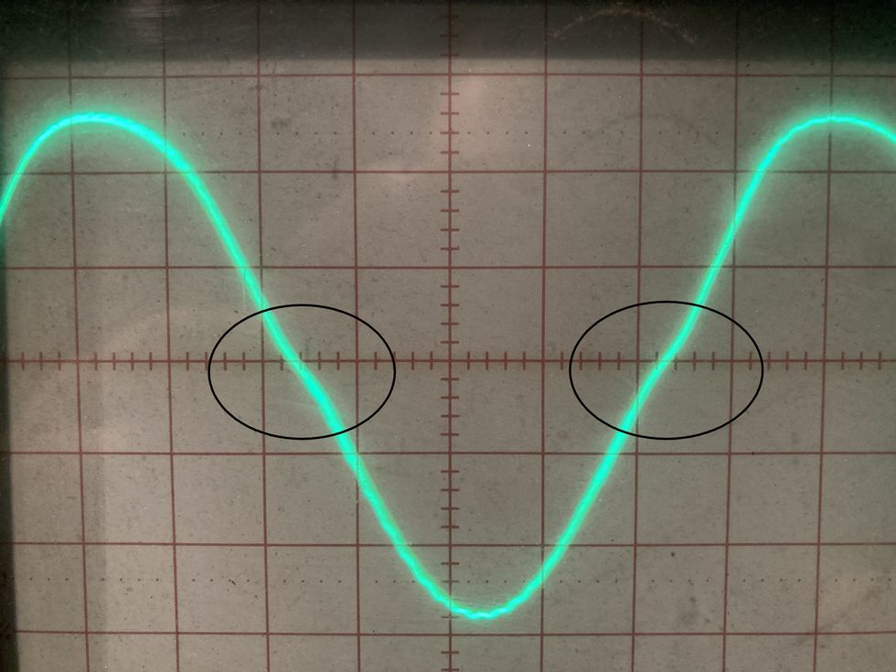
The designation of "class A" is often a topic of hot debate for some tube-amp enthusiasts. A guitar amp can run its tubes in class A, class AB, or class B. (Other classes exist, but not for audio applications.) Class A describes an amp in which a power tube conducts the entire sine wave of the guitar signal. Amps with two power tubes can divide that signal between the tubes, with one handling the "down" half of the guitar signal's sine wave and the other handling the "up" half. It's also referred to as "push-pull" operation. A perfect division between the halves is class B. In class AB operation—which is typical for many amps with two power tubes—each tube handles more than half, but not the full wave.
Any amp with a single power tube (aka "single-ended" amps) will always be class A—that single tube must handle the entire wave. That means our AC4 is class A, too. That said, amps with four power tubes typically pair two sets of class-AB-operating tubes, working much like a two-tube amp but adding power to each half of the sine wave. Similarly, amps with more than one power tube can still achieve single-ended, class-A operation by wiring two tubes in parallel. This allows them to essentially act as a single, more-powerful tube (the Gibson GA-8 is a good example of this).
Tube Diagrams
Note that the arrangement of elements in a tube diagram is schematic, not actual. In the EL84, for instance, the cathode sits in the center of the tube, with the filament located inside the cathode. The other elements (grid, screen, suppressor, and plate) surround the cathode, in that order.
The cathode and plate are made from bent metal. The grid, screen, and suppressor, however, are wrapped wires. That's how the electrons can travel almost unimpeded from the cathode to the plate—there's space between the wire wraps.
Dotted lines in the tube diagram for the grid, screen, and suppressor reflect the fact that these elements are wire wraps, not solid metal.
Let the Electrons Flow
Now that you know the fundamentals of a tube amplifier, take some time to study the amp schematic. (The AC4 schematic shown here has been redrawn, color-coded, and notated to help clarify the concepts.) It'll probably take several times of going over it to get things down, and you should always be very familiar with the schematic of any amp you're working on. Again, keep in mind that the voltages stored in amplifier capacitors are lethal. If you're not familiar with how to safely drain them of their charges, make sure you get a qualified amp technician to perform any mods or repairs.
If you'd like to start your journey toward being more proficient with amps, there are lots of great books and online sources that will help. Free PDFs of Navy Electricity and Electronics Training Series, Module 6—Introduction to Electronic Emission , Tubes, and Power Supplies are available online. Jack Darr's Electric Guitar Amplifier Handbook, Norman Crowhurst's Basic Audio, and Morgan Jones' Valve Amplifiers are also great books to track down—or you can try to locate a vintage RCA Receiving Tube Manual. If not, then simply warm up those tubes, crank the volume, play a power chord, and listen to those electrons flow!


![Rig Rundown: AFI [2025]](https://www.premierguitar.com/media-library/youtube.jpg?id=62064741&width=1245&height=700&quality=70&coordinates=0%2C0%2C0%2C0)