
Jeff,
I’m hoping you can help me. I recently bought a ’79 Fender Twin 135. When I removed the chassis, I discovered that the “hum balance” and “output tube matching” pots were disabled—no wires! Someone has done some mods, but I’d like to restore the amp to its original state. I’ve located the schematic, but I can’t find the right layout diagram. Also, the pot mounted in the output-tube-balance position has three lugs, but it appears that it should have four. Where would I even find a four-lug pot?
Thanks for your time!
Dave
Hi Dave,
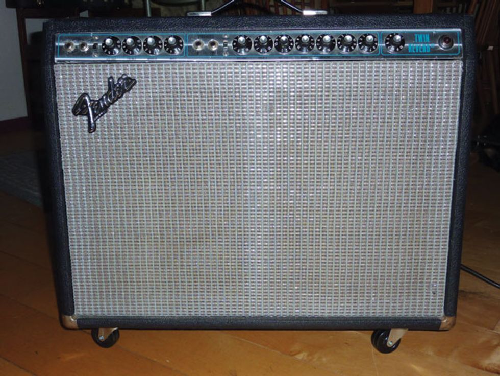
Let’s see if I can help. The 135-watt version of the Fender Twin Reverb (Photo 1) was produced from approximately 1977 through 1982. These amps were a bit different from their 100-watt silverface predecessors, notably because they used an “ultra-linear” output transformer. These transformers had an extra pair of leads tapped from the primary windings and connected directly to the screen grids of the output tubes. This type of output stage had previously been used mostly in hi-fidelity tube-amp design, and supposedly provides less distortion and better frequency response.
Oh, great! Just when guitarists had figured out that pushing the output stage into distortion leads to glorious tone, the engineers at Fender once again decided to “improve” their product! You’d think they would have learned from the original silverface-era “improvements,” but I digress. Anyway, let’s see if we can reinstall the missing pieces in your piece of late-70’s history.
I put substantial time into researching the availability of both the amp’s layout diagram and the four-lug output-tube-matching pot, and I could find neither. So I’ll resort to descriptions, pictures, and creative options.
Let’s start with the hum-balance control. The original part was a 100-ohm, 1-watt potentiometer with a screwdriver-adjustable recessed shaft. This pot, like the bias potentiometer we’ll be using, is still commercially available (try Angela Instruments), but if you need to get things going quickly, any standard 100-ohm (or even 250-ohm) pot should function just fine.
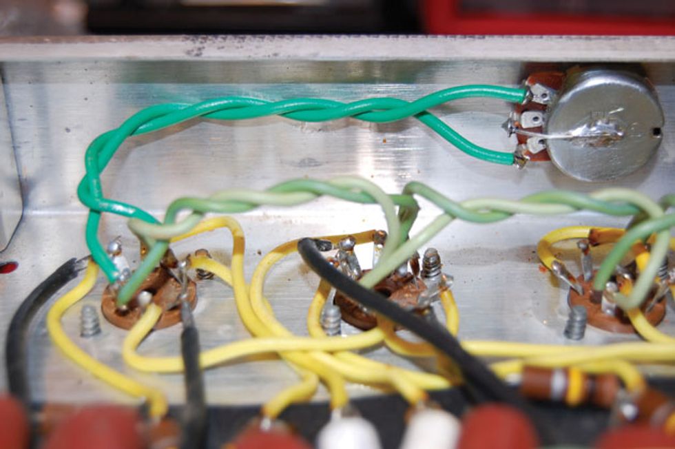
Photo 2
The wiring is pretty easy: Simply connect the clockwise and counterclockwise lugs to the two filament wires on the V1 socket. Next, connect the center lug to ground. You can do this the stock way, with a large ground lug mounted with the threaded bushing of the pot, or simply solder a wire to the body of the pot itself (Photo 2). That’s it for the hum balance, so on to the creative part.
Because the original four-lug output-tube-balance pot is no longer available, we need to find an alternative way to balance the output tubes. Balanced tubes in the output stage are a great idea, and I believe Fender engineers added this feature because tubes were still being made on old machinery. This machinery was not well maintained because—let’s face it—tubes were on their way out, and precision fell by the wayside. This led to tube sets that were not as closely matched as they’d once been, causing output-stage hum. Hence the output-tube-matching control, which alters the bias voltage on one side of the output stage relative to the other. This matches the total current flow of one half of the output transformer primary relative to the other half, eliminating hum. (This control was referred to as “hum balance” at the time.)
We really don’t need this function nowadays because matched output tube sets are readily available. I feel it’s better to install matched output tubes and turn this control into a true bias control, but since you seek the original function, I have a fix for you. (It comes to you from the creative Fender engineers responsible for the design of the Bassman model AB-165.)
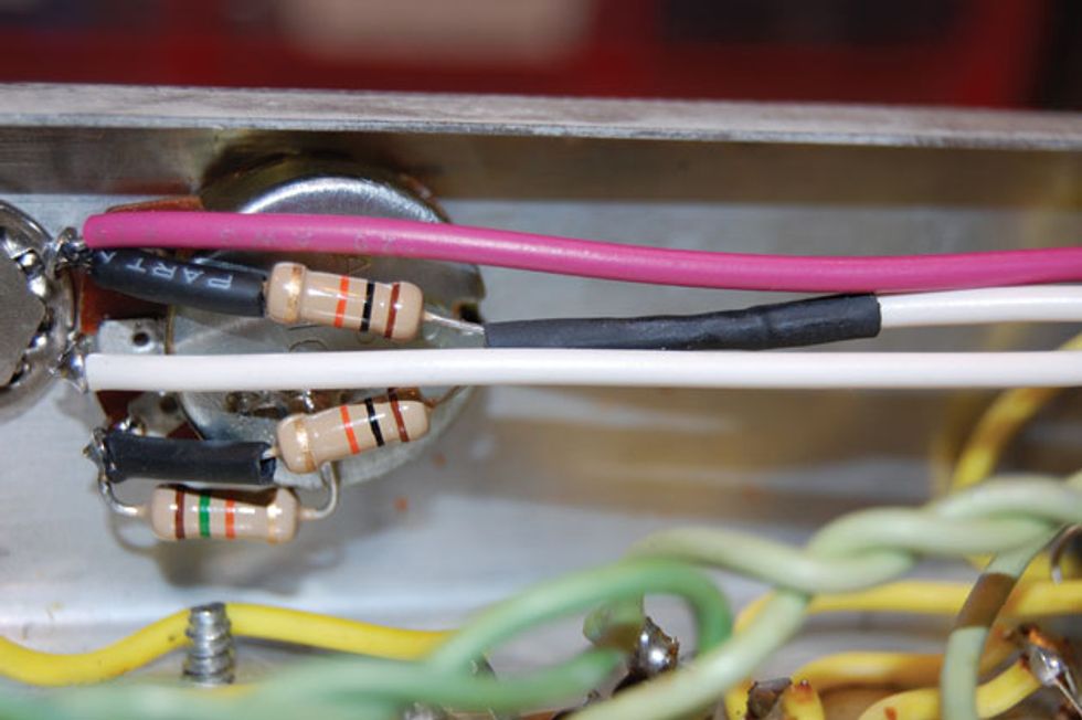
Photo 3
Install the currently available Fender 10k bias pot in its proper location on the rear panel. Next, attach the wire from the bias power supply board (the purple wire in Photo 3) to the counterclockwise leg of the control along with a 10k resistor, and solder these in place. On the clockwise leg, install another 10k resistor along with a 15k and solder. Connect the other end of the 15k resistor to ground by soldering it to the body of the pot, or a large ground lug if you have one. Twist together the ends of the two 10k resistors, and then solder them, along with a wire long enough to reach the bias resistors in the phase-inverter section of the circuit board. Finally, attach another wire to the pot’s center lug, again long enough to reach the phase-inverter section.
These two wires (the white wires in Photo 3) connect to the 47k and 68k bias resistors in the phase inverter. I prefer 220k resistors for both of these because they open up the phase inverter a bit, but stick with the original values if you want stock. Now, adjust this control according to the simple instructions from the Fender AB-165 schematic: “When installing new 6L6s, reset hum balance for min hum.”
There you have it: a balanced output stage. One problem, though—it’s balanced but not biased. When externally checking the tube bias, you may find that they’re under-biased (running too hot) due to the values of the new parts placing differing loads on the bias supply. My suggestion is to increase the value of the 15k resistor so it sets the tube bias where you want it. Or you could give yourself the ultimate setup and replace the 15k resistor with a 10k resistor and a 25k pot in series for true bias control, as well as balance. Twin function for your Twin amp!