Hi, Ask Amp Man fans. (Wow, say that three times fast.) Last month’s column featured some modifications to convert a ’70s Fender Twin Reverb back to blackface specs. This month’s highlights another possible silverface Twin modification—one that doesn’t improve the amp’s tone so much as its practicality in regards to operation and serviceability. We’re going to convert the bias circuit from a “balance” style back to the traditional “bias” style.
But before I get into the modification, here’s an email I received regarding my “The Early-’70s Silverface Fender Twin Reverb: Dud or Dynamo?” column. As expected, Premier Guitar readers are quite knowledgeable, and Joe Lehman shines a light on the nuances of the transition between the late-’67 and mid-’68 Twin.
Hi Jeff,
You state that the silverface amps first appeared in 1968. The Silverface trim was actually introduced around September ’67. The new Twin Reverbs kept the AB763 (blackface) circuit until May ’68, when they changed over to the less desirable AB568 circuit. Silverface Twins with the blackface circuit can be identified by the vertical black lines on their faceplates (a feature that Fender appears to have added to their new “’68 Custom” line of amps with early Silverface cosmetics). Needless to say, for fans of vintage silverface amps, the “black line” models of late ’67 and early ’68 represent something of a holy grail that combines classic tones with updated styling. The ultimate silverface Twins may be the very few black line amps that were ordered with JBL D-120 speakers. Those silver dust cones look way cool behind that turquoise and silver grille cloth, and the clean headroom is nothing but pure Fender goodness.
Cheers,
Joe Lehman
Thanks, Joe. Maybe that will help some of our readers find a pawnshop or yard sale prize someday. Now onto this circuit conversion.
While making the changes and “improvements” to these amps in the late ’60s, Fender decided to make a functional change in the bias supply area. The bias supply is a part of the power supply circuit that supplies a bias voltage to the output tubes in order to set their “idle” current. This is the amount of current the tube consumes before beginning to amplify the signal. In the blackface circuit, the same voltage was sent to all four output tubes, and was adjustable using the bias potentiometer, which enabled a tech to set tube voltage for proper operation. This method works well, provided that all the output tubes have manufacturing tolerances that respond similarly at the same bias voltage.
During the time of the silverface changes, Fender engineers converted this bias circuit to a “balance” circuit. The conjecture is that during this time in tube production, tube tolerances began to increase due to aging machinery that was probably not being maintained or replaced as needed. (I mean, why would manufacturers put money into this dinosaur of an electronic device, when everyone knew it was destined for replacement by this incredible new device called the transistor? But I digress.)
Changing to the balance circuit allowed the bias voltage applied to the push/pull output stage to differ between the push and pull sides, which would help eliminate the hum generated by unbalanced tubes. The one big problem with this circuit is that while you are able to set the voltage on both sides relative to each other, you are not able to set the absolute voltage needed to get the tubes into their optimal operating range.
I realize this concept may be a bit perplexing, but just know that since finding a set of matched, balanced, and currently manufactured tubes is now as easy as finding a replacement speaker, we will be converting the circuit back to one that lets you set your tubes to their optimal operating condition. (Note: You will need to have the amp re-biased after you perform this modification, just like you should any time you change a set of tubes.)
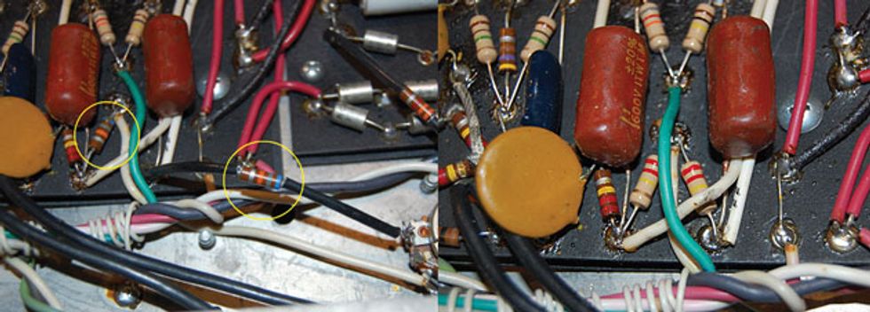
Fig. 1 (left) and Fig. 2 (right)
Step 1: Locate the two 68k (blue/gray/orange) resistors that connect to the 0.1 µF phase inverter capacitors (Fig. 1). One is on the board and the other is connected directly to the bias control. Remove these resistors and replace them with 220k (red/red/yellow) resistors, but there will be a location change here. The position of the original resistor on the board remains the same, but the second 220k resistor will also be mounted on the board, between the white bias voltage wire and the other 0.1 µF phase inverter cap, in mirror image of the original (Fig. 2).
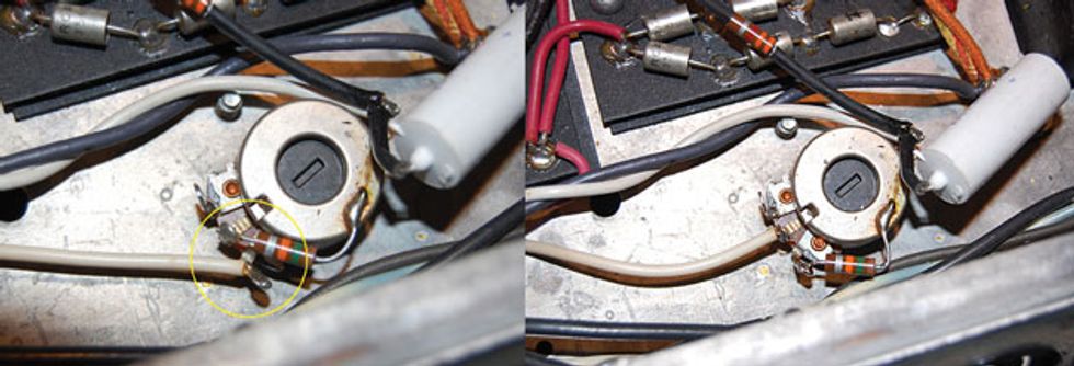
Fig. 3 (left) and Fig. 4 (right)
Step 2: Locate the white wire and the 15k (green/orange/gray) resistor on the bias pot (Fig. 3) and reverse their connections on the pot (Fig. 4).
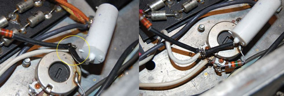
Fig. 5 (left) and Fig. 6 (right)
Step 3: The bias pot has a fourth terminal located on the bottom side. Connected to this are a white wire, a 3.3k resistor (orange/orange/red), and an 80 µF 75-volt capacitor (Fig. 5). Remove all three of these from this terminal and connect them to the remaining terminal on the top of the pot (Fig. 6).
That’s it. You’re done. Now you can have greater control over the bias of any set of matched tubes you decide to install in the amp.