Hi Jeff,
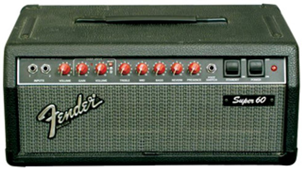
I have a stock Fender Super 60 head
and recently purchased a second one
without tubes. I want to do something
different with the second head
and was wondering if there’s any way
to modify it to get a JTM45 sound.
Do you have any suggestions?
Thanks,
Anthony Wright
Hi Anthony,
This could be an interesting project, but I do
need to preface it by saying there’s really no
way to transform your Fender Super 60 into
a Marshall JTM45 without, well, gutting the
entire amp and starting from scratch! While it’s
fun to note that the original Marshall JTM45
was actually a design that Ken Bran “borrowed”
from Leo’s Bassman (which in turn had
its origins in tube design manuals published
by RCA), different transformers with different
voltages and impedances, as well as substantial
differences in the circuitry will prevent us from
getting an authentic JTM45 sound and feel.
That said, there are quite a few changes you can make to the spare Super 60 that should give you a very different and very useable amp to complement your existing stock model. While there are many more complicated ways of modifying the amp, I’ll recommend changes you can make without cutting circuit traces or replacing pots, which are mounted in this amp’s circuit board.
One more point regarding the circuit board: The circuit traces in these amps are far from the best quality and can be easily damaged, so try to execute the changes carefully. Hopefully you’ll only need to do them once. Go online, grab a schematic for Fender’s Super 60 series tube amps, and let’s get started.
We’re going to begin at the input stage and work our way to the output. First, let’s change the components in the cathode circuit of V101. Remove R102 and C101 (1.5k and 10 μF respectively) and replace them with an 820 Ω resistor and a 250 μF capacitor. Although most of the resistors in this amp are 1/4 watt, I’d recommend using 1/2-watt resistors wherever and whenever possible for better reliability. While they are physically a bit larger and may possibly need to be elevated off the board a bit due to hole spacing, as long as the solder joints are sound this should not present a problem.
As for the 250 μF cap, anything 5 volts or higher will work fine—just be aware of the polarity and orient the cap properly. Next remove C102 (.0047 μF) and replace it with a .022 μF 400V or greater. Finally remove C1 (.022 μF) and replace it with a 500 pF cap. This can be of either silver mica or ceramic persuasion, and voltage is not an issue as no DC voltage is present here. That takes care of the input stage, so we’ll move to the tone stack next.
While the changes to the input stage will affect the amp’s gain and body, the tone stack is where the most noticeable change will take place, as it is the circuit most responsible for shaping the amp’s sonic signature. First, remove R10 (100k) and C4 (100 pF) and replace them with a 56k and 250 pF unit, respectively. Again, here you can use a silver mica or ceramic cap, but be sure it’s at least 400V DC.
Next remove C6 and C7 (0.1 μF and .047 μF) and replace them each with a 0.022 μF 400V. These changes play the biggest role in taking the amp from the American camp to the British camp. I employed this mod in a rotary “MF” (Marshall/Fender) switch on an amp I built for Stevie Ray.
Finally, remove C106 (22 μF) and R111 (3.3k) and install an 820 Ω resistor in the R111 position, leaving the C106 location empty. Now we’ll move on to the phase inverter stage.
Start by removing R134 and R137 (470k) and replacing each with a 1M resistor. Next remove R153 (680 Ω), replacing it with a 470 Ω, and R136 (6.8k), replacing it with a 10k.
Now remove C124 and C125 (.022 μF) and replace each with a 0.1 μF. Here, I prefer using 600V to 630V DC caps as the voltages are a bit higher. (Excluding the 250 μF cathode cap, it’s fine to use 600V to 630V caps for all the caps I’ve mentioned. That’s what I use in all the amps I build, along with 1-watt resistors. It’s the best way to ensure failure-free performance.) Finally remove R138 (6.8k) and replace it with a 4.7k.
There you have it. This should give you a normal channel that definitely has a foot planted in JTM45 tone. While I did not specifically address the characteristics of the Super 60’s distortion channel, it too will definitely have a more British tonality, and you may notice a bit of increased gain as well. A bonus! (Assuming that’s what you’re looking for.)
As far as tubes are concerned, since the original JTM45 came equipped with KT66s, the British version of the American 6L6, I thought I’d leave the Fender’s 6L6s intact, alleviating the need to convert to an EL34-based output stage. To do that properly, you’d have to install an appropriate output transformer, which would require substantially more money, time, and effort. I would have suggested changing the 6L6s to a pair of KT66s in the amp, but if memory serves, the Super 60 doesn’t provide sufficient tube spacing for these behemoths!
One other tube position to consider would be the phase inverter (V102). The stock tube in this location is a 12AT7, but if you’d like to get a bit more drive or push out of the amp, try installing a 12AX7, as the JTM would have had.
Now I hope you can get some super leads from your Super 60.
Warning: All tube amplifiers contain lethal voltages. The most dangerous voltages are stored in electrolytic capacitors, even after the amp has been unplugged from the wall. Before you touch anything inside the amp chassis, it’s imperative that these capacitors are discharged. If you are unsure of this procedure, consult your local amp tech.
 Jeff Bober is one of
the godfathers of the
low-wattage amp revolution,
co-founded and was
the principal designer for
Budda Amplification. Jeff recently launched EAST
Amplification, and he can be reached at
pgampman@gmail.com.
Jeff Bober is one of
the godfathers of the
low-wattage amp revolution,
co-founded and was
the principal designer for
Budda Amplification. Jeff recently launched EAST
Amplification, and he can be reached at
pgampman@gmail.com.