
In your guitar pedal dealings, you may have heard the phrase “component tolerances.” Nearly every component in a pedal is marked with a value, and ideally every component in your pedal would be that exact value, not one bit more and not one bit less. So, every 1k-ohm resistor would be exactly 1.0000000000000k ohm and every 10 µF capacitor would be exactly 10.0000000000000 µF. In this supernatural circuit situation, every pedal would sound identical. There would be no deviations from each component’s intended value, and there would be no deviations from the effect’s intended sound (all other things being equal). Unfortunately, we cannot hope to achieve this sort of metric perfection in the real world. While perfection may not ever be attained, it is also not often required, and all the circuits we interact with day in and day out can tolerate some sort of variation in their components’ value.
Your pedal’s designer specifies every component value in a design to result in a particular timbre or function and needs to know how much each component employed might vary from that specified value. When manufacturers make parts, they specify the nominal value and a particular tolerance value. Often, this tolerance is specified as a percentage of the nominal value. So, a 10-percent tolerance in a 1k-ohm resistor could be anywhere from 900 ohms and 1100 ohms. The higher the tolerance figure, the more variation you can expect in the value of a given component.
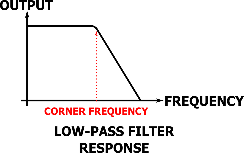
Fig. 2
While more variation may seem like strictly bad news at first blush, it does have some benefits—principally, cost. The machines and processes required to make a one-percent resistor are cheaper and faster than those required to make a resistor of arbitrarily higher precision. Consequently, a run-of-the-mill one-percent tolerance resistor may cost five cents while its 0.005-percent laser-trimmed counterpart costs $12. If vintage pedal prices are starting to make you queasy, know that it could be much worse. Demand plays a major role in cost as well, as it is pretty rare that you need a 0.005-percent resistor.
So, what difference does tolerance make and how do we know when we need to splurge for the caviar components? Without getting too far into the mathematical weeds, here’s a couple examples. Take Fig. 1, where a very simple resistor/capacitor low-pass filter is shown. This filter’s corner frequency [Fig. 2] is determined by the value of the resistor and capacitor, and that frequency has a certain sensitivity to variations of those values. [Note: The corner frequency is also known as the cut-off frequency—frequencies above this point will be attenuated by the low-pass filter.] In this particular circuit, if we wiggle the capacitance value by 10 percent, the corner frequency will move by approximately 10 percent.

Fig. 3
The corner frequency of the inductor/capacitor low-pass filter in Fig. 3 has a different sensitivity to changes in the value of the capacitor. If we increase the value of the capacitor by 10 percent, the corner frequency of the filter moves by approximately five percent. So, we can say that the corner frequency of the Fig. 3 circuit is less sensitive to changes in the capacitance than the Fig. 1 circuit. If you want to build circuits that are more forgiving of changes in component values, you can make some design decisions that will help!
You can also quantify what difference component variation will make in the context of your particular application. Let’s assume we’re employing the circuit in Fig. 1 as a pedal power supply filter. Let’s set resistance at 470 ohms and capacitance at 220 µF. We know we’re primarily wanting to filter 60 Hz hum from our power line, and at this nominal value of R (resistance) and C (capacitance), we can attenuate 60 Hz by approximately 32 dB. If we choose a 20-percent capacitor, in the worst case, our C drops 20 percent to 176 µF and we only reduce that 60 Hz noise by 30 dB. In practice, that difference of 2 dB probably won’t result in a dramatic difference in performance. This tolerance to higher tolerance parts is one of the reasons why we see 20-percent capacitors in big power supplies. When bigger is better, some amount of overkill can make variations in value a non-issue, practically.
Whether you’re bending your own circuits or just trying to figure out why you can’t find a backup that’s quite as good as your No. 1 dirtbox, you might consider how the imperfections in those little devices inside our devices add up to make something special.