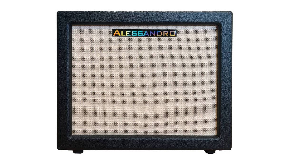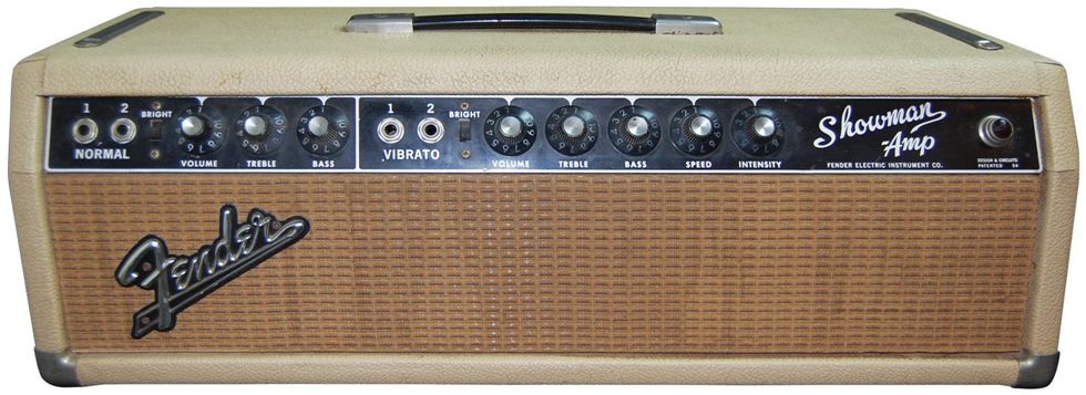

Hello Ask Amp Man fans! Once again, just when I think I’ve seen about every iteration of vintage Fender amp, another interesting one crosses my bench. This month’s beauty is a blonde 1963 Showman head (Photo 1) that just came into the shop.
You ask, “What’s so special about that?” Granted, we’ve all seen blonde Fender Showman amps before—at least those of us who are fortunate enough to see lots of great vintage gear have—but this one is transitional. Not just because it’s a blonde cabinet with a blackface control panel, but because it has some very rare transitional output tubes as well.
7355 output tube.
If there’s one thing vintage Fender amps are known for, it’s their use of 6L6 (5881) and 6V6 output tubes—as opposed to their EL34 and EL84 counterparts utilized in amps produced across the pond. This was pretty much ubiquitous across the historic Fender product line and was responsible, in large part, for giving the company’s amps their signature “American” sound.
Hi-fi vibe. So why change for this amp? That question may never be answered, but my baseless possible theory is Fender may have wanted a more hi-fi sound from the amp—something with more fidelity—so they opted to use the 7355 output tube. Around the same time, Ampeg was producing amps utilizing the 7591 output tube, which is also a hi-fi-style tube. The Ampegs were great-sounding amps, so maybe Fender took a cue from the guys on the East Coast. I’ve also read there may have been availability issues in obtaining 6L6s at this time. Who knows?
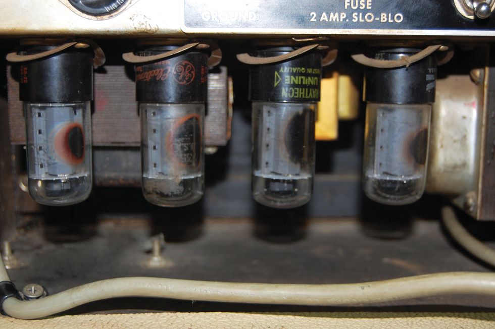
Photo 2
Anyway, the problem here is the 7355 is rated at a maximum plate dissipation of 18 watts, while the typical 6L6/5881 is rated for a maximum of 30 watts. Unfortunately, tube data is not provided in any sort of standard format, so attempting to compare tube specs on an apples-to-apples basis is difficult at best, but tube data suggests output from a pair of 6L6 tubes can be in the 50-plus watt range, which is typical, and that the output from a pair of 7355s can be 40 watts, which is past the amp’s stated design maximum of 36 watts (18 watts each).
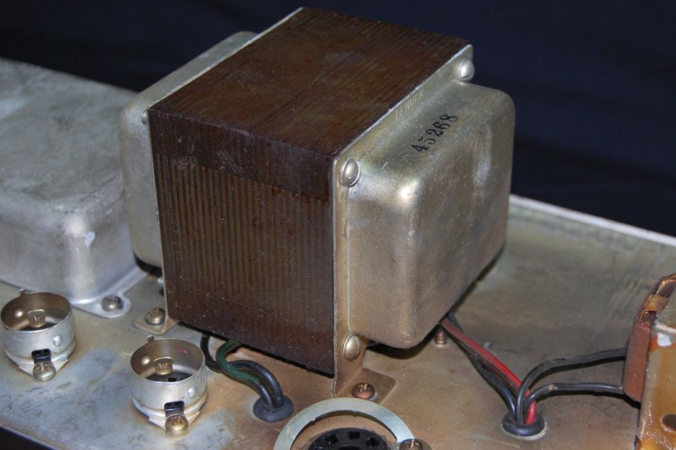
Photo 3
That said, maybe they were hoping to design an 80-watt amp with a better frequency response. Again, who knows? But a quick look at these tubes (Photo 2), which are no bigger than 6V6 tubes, screams “good luck!” On top of that, Fender was following up the blonde 1961 Showman (model 6G14) and 1962 Twin (model 6G8), which were 80 watts and had a quad of 5881s and a huge chunk of iron for an output transformer (#45268) (Photo 3). This four-output-tube amp is using undersized tubes and a redesigned output transformer that is half the size (#125A18A) (Photo 4). That doesn’t quite sound like a recipe for success to me.
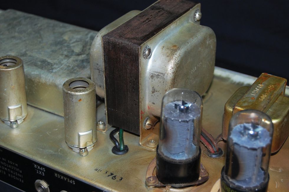
Photo 4
The plot thickens. And there are even more questions. According to the tube chart, this is a Showman amp, model AA-763 (Photo 5), but not according to schematics. In fact, no schematic that I could find reflects the use of 7355 output tubes or the 125A18A output transformer. Furthermore, the name “Showman-Amp”—as it appears on the faceplate—has typically denoted a single-speaker cabinet, while the name “Dual-Showman” designated a two-speaker cabinet. Apparently not so here, because the owner claims his dual 15” cabinet is the stock, matching cabinet for this particular head.
WARNING:
All tube amplifiers contain lethal voltages. The most dangerous voltages are stored in electrolytic capacitors, even after the amp has been unplugged from the wall. Before you touch anything inside the amp chassis, it’s imperative that these capacitors are discharged. If you are unsure of this procedure, consult your local amp tech.This normally would be easy to discern, as the blackface Showman and Dual Showman amps this model quickly morphed into utilized specific output transformers depending on the speaker load. The Showman used the 125A30A for an 8-ohm load and the Dual Showman used the 125A29A for a 4-ohm load. There is, however, a bit of information gleaned from researching more transformer history that may fill in the blank here. There was a blonde Fender Twin-Amp manufactured for a very short time as well. It’s possibly even more rare and short-lived than this Showman on my workbench, and was built with 7591 output tubes and utilized the same transformers as this Showman. Since the specs of the 7591 and 7355 output tubes are relatively close and the Twin-Amp combo is, of course, a 2x12 with a total load of 4 ohms, one may assume the output impedance of the A18A transformer to be 4 ohms and that the 2x15 cabinet could indeed be its mate. Boy, that was a long way home!
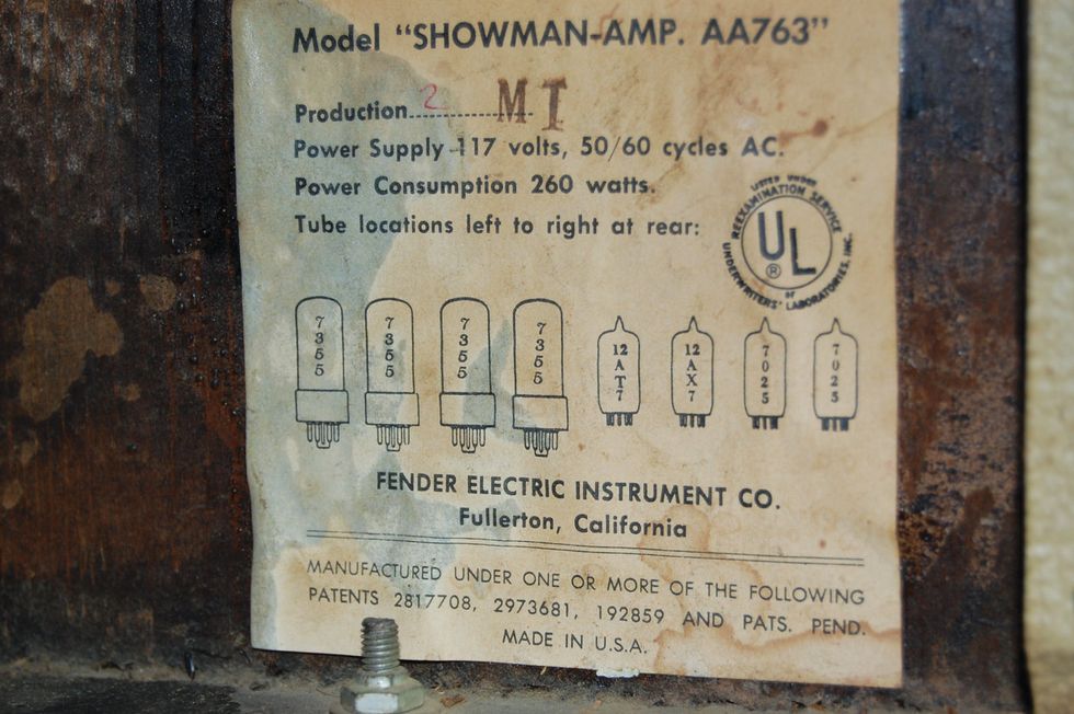
Photo 5
Anyway, this also provided me with some useful service information regarding output tube replacement/substitution, because they did need to be replaced, since most OEM tubes by this time have been run ragged and are probably as microphonic as the day is long. The first inclination would be to replace the 7355s with a typical 6L6, but that’s probably not a good idea. Not only would the sockets need to be rewired, but primary impedance of the output transformer is not a great match and the filaments of the 6L6 draw more current and would put additional load on an old mains transformer that, theoretically, is already running on more wall voltage than it was originally designed for. The better solution would be the 7591s, as they are currently manufactured and available. The 7355s were obviously produced with unobtainium, since they’re virtually unavailable in the NOS market and no one has done a reproduction. The 7591s, in my opinion, are also a better sounding tube, so they make a great replacement for the 7355s.
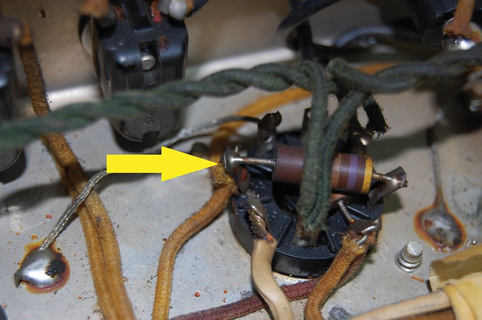
Photo 6
There will, unfortunately, be a couple modifications necessary. (And, as always, unplug the amp and drain the power supply caps before servicing any amp. If you don’t know how, find someone that does!) First, the 470-ohm screen grid resistor and associated wiring needs to be disconnected from pin 4 of every socket (Photo 6). Then stand the resistor, still connected to pin 8, up in the air and reconnect the wires to the top of the resistor that were disconnected from that socket. Do this for all four sockets and resistors. Be sure they won’t come in contact with the inside of the cabinet once the head is reassembled. You may need to bend them down to be sure of this. Next, there may be a change in the bias supply voltage necessary, as the 7591s require less negative voltage. Unfortunately, you cannot measure the bias current using a standard octal socket bias-measuring device, but to measure the current, connect a 1-ohm resistor between pin 5 and the ground on the output tube socket, and measure across it. It’s a 1:1 ratio, so a reading of 30 mV is equal to 30 mA of current.
Well, there you have the story of a rare beast, although we may never know why it exists.
’Till next time…