It’s in a guitarist’s nature, I believe, that we can’t leave well enough alone. Most of us have an ideal sound (or sounds) in our heads, and we won’t rest until our vision is realized. We can have a perfectly fine guitar or amplifier, but we still have an inherent urge to tinker with it until it’s “just right” in feel or tone. On this premise—as well as the fact that many of us are on budgets that don’t allow us to buy every amp that strikes our fancy—the idea of modifying an amp we already own strikes a very appealing chord for many players.
Of course, before beginning any sort of amp modification, you’ve got to pinpoint exactly what you want to accomplish. And you have to keep in mind that an amp is full of many parts that interact with and affect one another, so even small changes to any of these parts can yield major differences in tone and performance. However, this exponential effect that small changes can have on tone means there are many relatively easy ways in which even inexperienced but adventurous DIYers can mod their amp.
Here we present eight short projects that pretty much anyone with rudimentary soldering skills can tackle. Even better, the mods we’re detailing here are all reversible. So if they don’t suit your fancy or you need to return your amp to its stock circuitry (for example, to sell it), you can do so without much trouble.
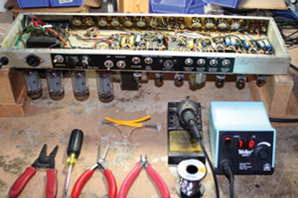
No job can be done well without the proper tools—in fact, attempting to do so usually results in a nightmare of frustration. For the mods we’re exploring here, I recommend the following tools:
• Standard-size
Phillips and/or flat
screwdrivers (for
re-moving and securing
the chassis)
• Wire cutters/strippers
• 25–40-watt
soldering iron
• Acid-free rosin
core solder
• Safety goggles
• Needle-nosed pliers
• A copy of your
amp’s circuitry
schematic
Mod 1:
Swap Preamp Tubes to Adjust Headroom
One of the most common things guitarists request from us at our shop (schroederaudioinc. com) is the ability to get more or less headroom—either cleaner tones at higher volumes or more overdrive or distortion at lower volumes. Let’s begin by looking at some simple ways to alter your amp’s headroom.
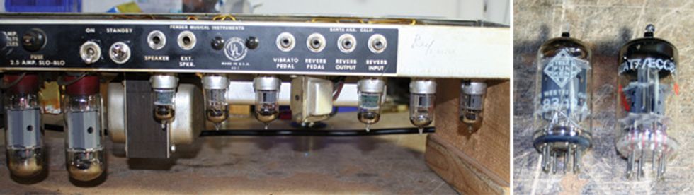
Left: You can alter your amp’s headroom
by swapping out the first preamp tube in its
first gain stage—typically the small tube furthest
from the power tubes. In this picture
of a Fender Twin Reverb amp chassis, the
power amp tubes are the two large glass
bottle-like things at far left, which means
the first preamp tube of the first gain stage
is the small valve at far right. The phase
inverter preamp tube is the third from left.
Right: A 12AX7 preamp tube (aka ECC83,
left) typically has a gain rating of 100
and yields more distortion, while a 12AT7
(ECC81) has a cleaner gain rating of 70.
The first preamp tube (aka “valve”) in an amp’s circuit is used in its first gain stage(s) of an amp. It’s usually a 12AX7 (aka an ECC83 in Europe and abroad), and it’s the small tube located farthest from the larger power tubes. Typically, a 12AX7 has a gain rating of 100. One simply way to achieve more headroom in your amp is to replace this tube with a 12AT7 (aka ECC81), which has a gain rating of about 70 and will yield cleaner sounds than a 12AX7. Conversely, players who have an amp with a 12AT7 in the first gain stage can get more gain and overdrive from their amp by swapping it for a 12AX7.
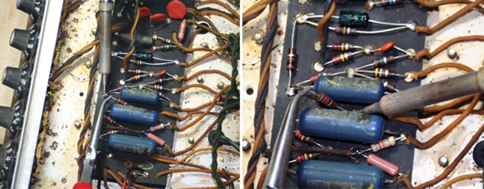
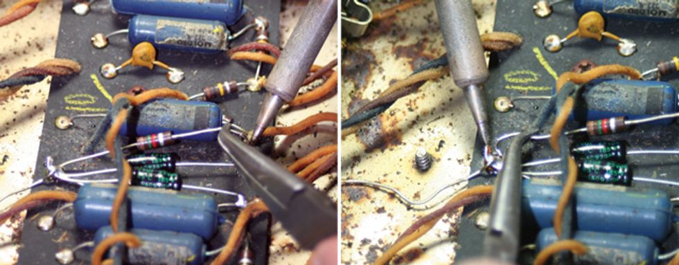
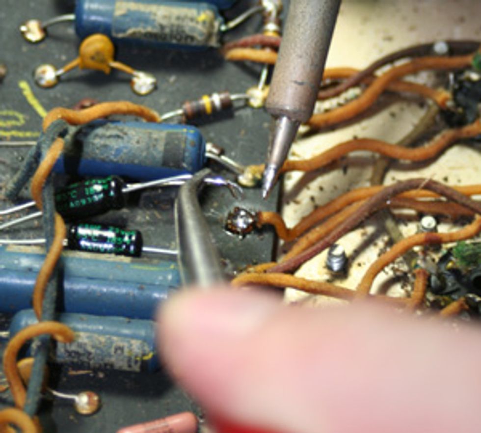
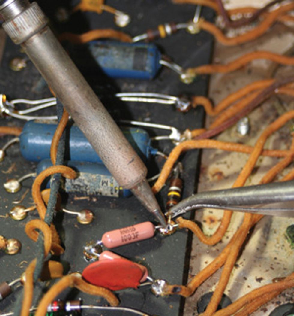
Amp headroom can also be adjusted by swapping the resistor in a
negative-feedback circuit for a different value. Here, the resistor ringed
with gray, red, brown, and silver value marks is being desoldered, one
lead at a time, to make way for another.
You can further alter your amp’s headroom by simply changing its phase inverter, which is the preamp tube located right next to the power tubes. It sends the signal from the preamp into the power amp, and swapping it with one that has a higher or lower gain rating (i.e., a 12AX7 vs. a 12AT7) will also adjust the amount of gain being sent to the amp’s power tubes.
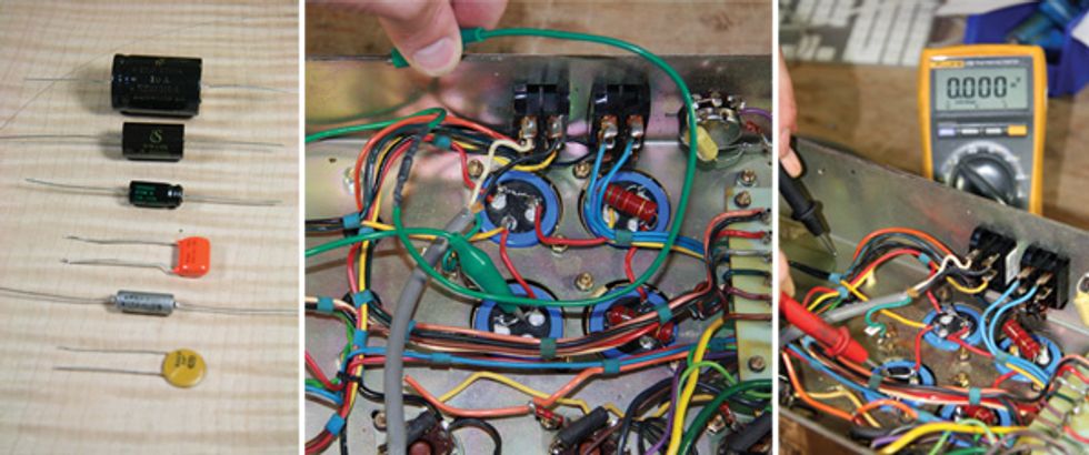
Middle: Before touching anything inside the chassis of a tube amp, bleed off any lingering fatal voltages being stored inside by attaching one end of a 100 kΩ resistor (inside the black shrink wrap in the middle of the green wire) to ground and touching the other end to the positive side of each electrolytic cap in the circuit (the blue ones) for a full minute each.
Right: To confi rm that voltage has been discharged, measure each cap with a voltmeter set to DC voltage and make sure none is detected. Touch the black lead to the chassis, and the red lead to the positive cap terminal.
All amplifiers contain lethal voltages. If after reading through this entire article you still feel unsure of your capabilities, please refrain from performing any modifi cation to your amp. If you decide to proceed, make certain the amp is unplugged and that all tubes have been removed before beginning. Next, remove the amp chassis from the box it is housed in and turn it upside down so the circuitry is exposed and easy to work on.
The most dangerous voltages in an amp are stored in electrolytic capacitors, even after the amp has been unplugged from the wall. It’s imperative that these capacitors are discharged before proceeding with any work on the amp. The best way to do this is with an alligator clip wire with a 100K resistor in series to ground. Clip one end of the wire to ground and the other end to the positive side of each electrolytic capacitor. This will bleed off any voltage that may be stored in the capacitor. To be certain all voltage is discharged, use a voltmeter set to DC voltage. After about a minute, the capacitors should be fully discharged. If you are unsure of this procedure, consult your local amp tech.
Mod 2:
Swap Negative-Feedback Circuit
Resistors to Adjust Headroom
Be careful not to leave the soldering iron on the solder joint for too long as doing so could damage the component.
Another way to increase your amp’s headroom is to adjust the size of the negativefeedback resistor. Because the earliest tube guitar amps from the 1950s weren’t intended to overdrive (though it wouldn’t be long before rock ’n’ roll pioneers harnessed the glorious sound), the negativefeedback circuit was implemented as a way to reduce distortion. It does so by taking a very small signal from the amp’s output and injecting it back into the gain stage— only it’s out of phase with the output. This causes phase cancellation and affects the amp’s overall gain character.
The negative feedback resistor located off of the amplifier’s output jack. Decreasing its value will increase your amp’s overall headroom. In the photo above, the feedback resistor is located between the top two blue coupling capacitors—it’s the component with (left to right) gray, red, brown, and silver bands on it, and one of its leads is being gripped by needle-nose pliers. (For complete information on how to read resistor color codes, visit wikipedia.org and search for the “Electronic color code” entry.)
To remove the current resistor and
install a new one:
• If you have a soldering iron that
lets you set exact temperature, set
it for between 700 and 800 degrees
Fahrenheit.
• Heat the solder joint on one end of
the feedback resistor and gently lift it
out of the circuit, then do the other.
• Bend the tips of the new resistor’s
leads to fit neatly in the two vacated
solder joints.
• Snip off excess length on the leads of
the new resistor.
• Heat one of the solder joints and put
one end of the resistor in place, and
then proceed to the other solder joint.
• Add a bit of solder to the new solder
joints so that there’s a solid connection.
• Repeat the steps above with different
value resistors until you are satisfied with
the increase or decrease in headroom.
Mod 3:
Swap the Cathode Resistor
to Adjust Headroom
Shown here is our Fender Twin Reverb. Its 1.5k Ω cathode resistor is marked by the brown, green, red, and silver bands.
Adjusting the value of the resistor connected to the cathode (the main filament-like part that forms the core of a vacuum tube) of any of the gain-stage preamp tubes can greatly affect the overdrive capabilities and headroom. The bias of a preamp tube— how much voltage is running through it— occurs in the tube’s cathode.
Not all amps have a cathode resistor, but when they do, it’s wired in parallel with a cathode capacitor—which can also be swapped out for one with a different value to increase or decrease headroom (see Mod 4, below, for more on this).
Generally, the range of values for the cathode resistor is 820 ohms (Ω) to 10 kΩ, but the most common value is 1.5 kΩ. Decreasing the value causes the tube to bias hotter, which in turn causes the tube to overdrive quicker, yielding a hairier tone due to the increase in gain. It follows that increasing the value of the cathode resistor causes the tube to bias cooler, lowering the gain of the tube and thus increasing clean headroom. To change the value of the cathode resistor, refer to the steps in the Mod 2: Swap Negative- Feedback Circuit Resistors to Adjust Headroom section.
Mod 4:
Swap the Cathode Capacitor
to Adjust Headroom
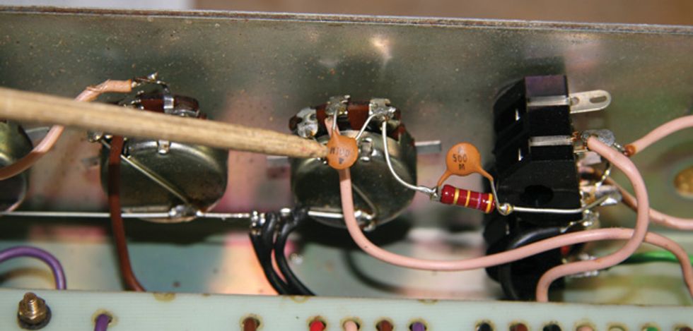
To increase or decrease gain, you can swap out the cathode capacitor (here, it’s the black component with green writing) with one of a different value—a lower value for more gain, higher for more dirt.
As mentioned above, the cathode capacitor also has a significant effect on an amp’s available gain. The larger the value of the cathode capacitor, the more low end is accentuated in that gain stage. The smaller the value of the cathode cap, the more high end is accentuated. The typical range of cathode capacitor values is anywhere from .68 μf to 250 μf. A typical cathode cap value in lower-gain amps (including the Fender Twin we’ve been working on here) is 25 μf. In higher-gain amps such as a Marshall Super Lead, you would expect to see a cap value of .68 μf. The reason higher gain amps use cathode caps with such small values (especially in the early gain stages) is to tame the potential for too much bass to be amplified—which could result in the amp sounding too muddy when pushed into overdrive.
Some amplifiers—including old Supros and Magnatones—do not have cathode caps on the first gain stage(s). You can increase the gain of these amps by adding a cathode capacitor in parallel with the cathode resistor of that gain stage. To change the value of this cathode capacitor, follow the rules for changing a resistor in the two previous sections.
Cathode capacitors are often electrolytic—meaning, they store electrical charges and therefore have + and – poles that must be installed in the proper direction. It’s therefore imperative that you pay special attention to where the existing capacitor’s + and – poles are oriented before removing it. The negative side must be attached to ground, and the positive side of most electrolytic caps is the side with a lip near the end. The negative side will not have such a lip and will be flat.
Mod 5:
Swapping the Coupling
Capacitors to Adjust Bass
Response
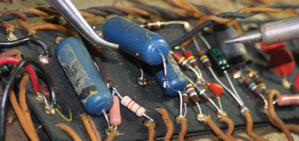
To alter bass response, you can swap coupling caps for different values. In our Twin Reverb example, the coupling caps are the two blue cylinders at the
end of the circuit board (closest to the power tubes).
The second most common request we get at our shop is to change the overall tonal character of an amplifier. As with changing an amp’s gain, small changes in the circuit can greatly affect the tone.
If you’re looking to get more (or less) bass out of your amp, its coupling caps—which act as frequency filters—are great candidates for modification. Coupling capacitors typically have values from .022 μf to .1 μf. The purpose of coupling caps is to block DC voltage and can be found in several places in the circuit. The specific ones that we’ll be dealing with are situated between the phase inverter plates and the power-tube grids. Smaller values such as .022 μf attenuate the bass in the preamp, preventing it from being passed into the power amp section. Larger values such as .1 μf allow more bass to pass through. In a bass amp, you may see up to .47 μf.
Naturally, the idea when modifying coupling capacitors is to get the great bass response you desire without causing the amp to sound too boomy. High-gain amps typically have a smaller value than clean amps for this reason.
Coupling caps are rarely electrolytic and will therefore function without regard to polarity. That said, certain types of coupling caps—including film and paper-in-oil varieties—may yield small sonic differences depending on the direction of travel.
Mod 6:
Swapping Tone-Stack Resistors
Another way to alter your amp’s frequency response is to swap the slope resistor for one of another value. In this picture of our Twin, it’s the one with brown, black, yellow, and silver bands being gripped by one lead with needle-nose pliers.
The part of an amp’s circuit that governs the ranges of its tone controls is known as the tone stack. This part of the circuit is most commonly a combination of three potentiometers (for bass, mid, and treble knobs), three capacitors, and a resistor called the slope resistor. One simple mod that will change the tonal character of your amp is to experiment with the value of the slope resistor, which controls how frequencies are divided over each tone control. Simply put, the slope resistor changes the slope of the midrange dip if it were charted on a frequency-response chart.
Typical slope-resistor values range from 33 kΩ to 100 kΩ. A larger value yields a sound with more of a midrange scoop (i.e., where treble and bass frequencies are louder than the mids). Smaller values accentuate midrange. In our Twin Reverb, the vibrato channel’s slope resistor is the 100 kΩ one (with brown, black, and yellow rings) attached to a 100 kΩ resistor on one end and two blue .1 μf coupling capacitors on the other. To change the value of the slope resistor, follow the previous instructions on how to replace a resistor.
Mod 7:
Removing the Bright Cap to
Tame Harsh Treble
To tame treble response in a Marshall head, simply clip or desolder the bright cap on the volume pot.
In case you decide to reverse the mod in the future, make sure you leave as much of the capacitor’s
leads intact (if you decide to clip it) to facilitate easy reinstallation.
If your amp has a treble response that feels too harsh to your ears—especially at lower volumes—you can tame it by removing the bright cap. In a Marshall amplifier such as a Super Lead, you simply remove the capacitor that lies across two legs of the volume pot. This cap allows the high frequencies in the guitar signal to bypass being attenuated by the taper of the volume pot, so removing this cap eliminates the amp’s severe-sounding highs at lower volumes.
To remove a bright cap, simply desolder the leads or clip them at a point near the lugs on the pot. Be sure to leave enough lead on the cap so that, if you later decide to reinstall it, there will be enough length left to be able to solder it back into place.
Mod 8:
Adding Shielded Wire to
Reduce Noise
If your amp has a lot of hiss and background noise, you may want to check and see if the wire connecting the input jack to the grid of the first preamp
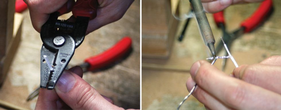
tube are made with unshielded wire. If so, replacing it with shielded wire should decrease noise. Here, we’re stripping the shielding from one lead prior
to soldering the connection, then tinning the gathered shielding lead that we’ll solder to the input-jack side.
Our final project here is a mod that will subdue hiss or unwanted background noise in your amp. A lot of the time when an amp is plagued with this malady, it’s because it uses unshielded wiring in key sections of the circuit. Strategically replacing these lengths with shielded wire is a fast, easy way to improve the amp’s noise floor.
Perhaps the best place to start adding shielded wire is the section going from the amp’s 1/4" input jack to the grid of the first preamp tube. The grid in question for a 12AX7/ECC83 or 12AT7/ECC81 tube socket will be pin number 2. Any noise picked up in this part of the signal path is passed through each of the amp’s gain stages, getting amplified each time, so adding a shielded wire here should yield significant noise reduction.
To perform this mod on an amp like our
Twin Reverb:
• Snip the lead or desolder the wire
where it attaches to the input jack.
(A standard soldering iron will work
for desoldering, but a solder sucker/
desoldering pump will create a cleaner
joint for the new connection by
removing excess solder.)
• Snip or desolder the other lead where
it attaches to the grid pin of the preamp
tube. The grid on a 12AX7 will
be pin 2 or 7
• Solder the two leads from a length
of new shielded wire to the newly
vacated spots.
Ground the new wire by soldering the shielding on the input-jack side to the ground on the input jack. On a vintage Fender-style amp, this is the lug that is making contact with the chassis. Only ground this shield on one end.
It’s a good idea to tin the leads of the wire you are installing before attempting to solder it into place. To do this, simply wick a small amount of solder onto each bare end of the new wire. Tinning the new wire before installing it improves the quality of connection it makes in the circuit.
Often the shielding on shielded wire is braided and needs to be unwound. I like to use a pointed object to get between the braided fibers to unravel them. Once you’ve unraveled enough shielding on the end that will be attached to the input jack, gently twist the fibers together to create one uniform shieldedwire lead—which you’ll then want to tin.
Go Forth and Mod
I hope you’ve found some modifications
here that seem like projects worth pursuing
on one of your amps. Although these
projects yield pretty significant and impressive
results considering how little work is
involved, I know it can be pretty daunting
to poke around inside a device with
significant safety risks for the first time. The
safety measures we’ve outlined should alleviate
any danger, however if you have any
doubts about your ability to pull these off,
it’s always better to be safe than sorry. But
even if you decide to have a qualified tech
execute these mods for you, at least this
information will give you a better understanding
of some of the nuances and possibilities
of guitar amp modifying.