
The shopping list. You don't need much to build this tester. I'll go into more detail in a moment, but here are the items:
phase-testing device.
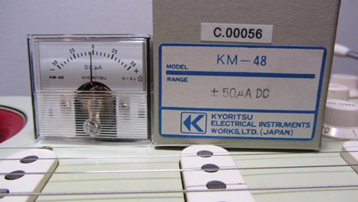
• An analog zero-center moving coil milliammeter with a sensitivity of +/- 50 µA DC. (If you're new to the term, Merriam-Webster defines milliammeter as “an instrument for measuring electric currents in milliamperes.")
• One case with four self-adhesive rubber feet to house the circuit.
• Two panel-mount 4 mm banana jacks (one red and one black).
• One small speaker terminal with clamp connectors
• Red and black wires.
For this column, I bought a '60s new-old-stock milliammeter on eBay for $5. I also dropped $8 on a Hammond 1594CBK ABS plastic case. (Because there's no shielding required for this project, a plastic case works fine. In fact, you can use whatever case material you want—wood, aluminum, sheet metal, or even cardboard.) Including shipping and the other small parts, I spent a little less than $20, which I think is a reasonable price for a professional phase-testing device. And let's not forget the priceless fun of building it! Photo 1 shows the meter and Photo 2 shows everything else.
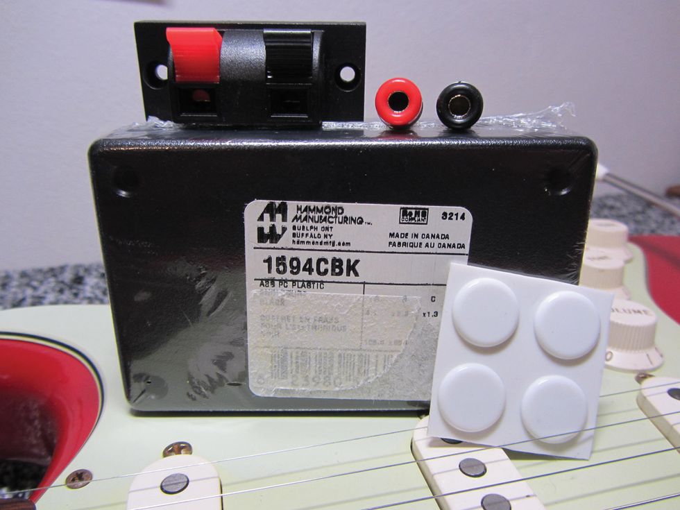
Photo 2 — Courtesy of singlecoil.com
Design details. I decided to use two different input stages: In addition to the two 4 mm banana plugs, I also wanted a small speaker terminal with clamp connectors. By clamping a pickup's two wires to the latter, you can determine its phase in seconds; the two banana plugs are perfect for connecting an existing circuit to the tester using standard laboratory measuring cables with 4 mm banana plugs.
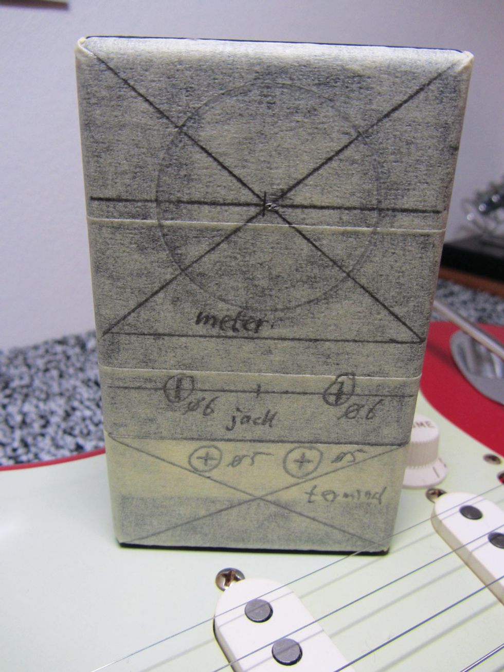
Photo 3 — Courtesy of singlecoil.com
Getting started. The first step is to prepare the case. To do this, I covered the front of the case with masking tape so I could pencil in where I wanted to place the individual parts (Photo 3).
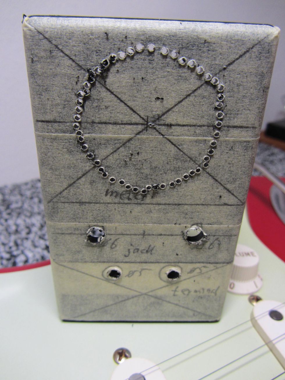
Photo 4 — Courtesy of singlecoil.com
Next, I drilled the holes for the two jacks and the speaker terminal. Then I drilled small holes in a circle that was sized to accommodate the meter (Photo 4).
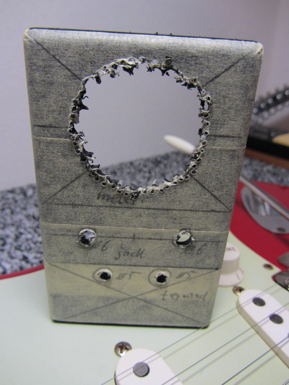
Photo 5 — Courtesy of singlecoil.com
By perforating the plastic this way, you're able to easily pop out the center circle and mount the meter in the exposed hole (Photo 5). After you install the meter, its frame will cover all your sloppy work, so you don't have to be over-precise at this stage.
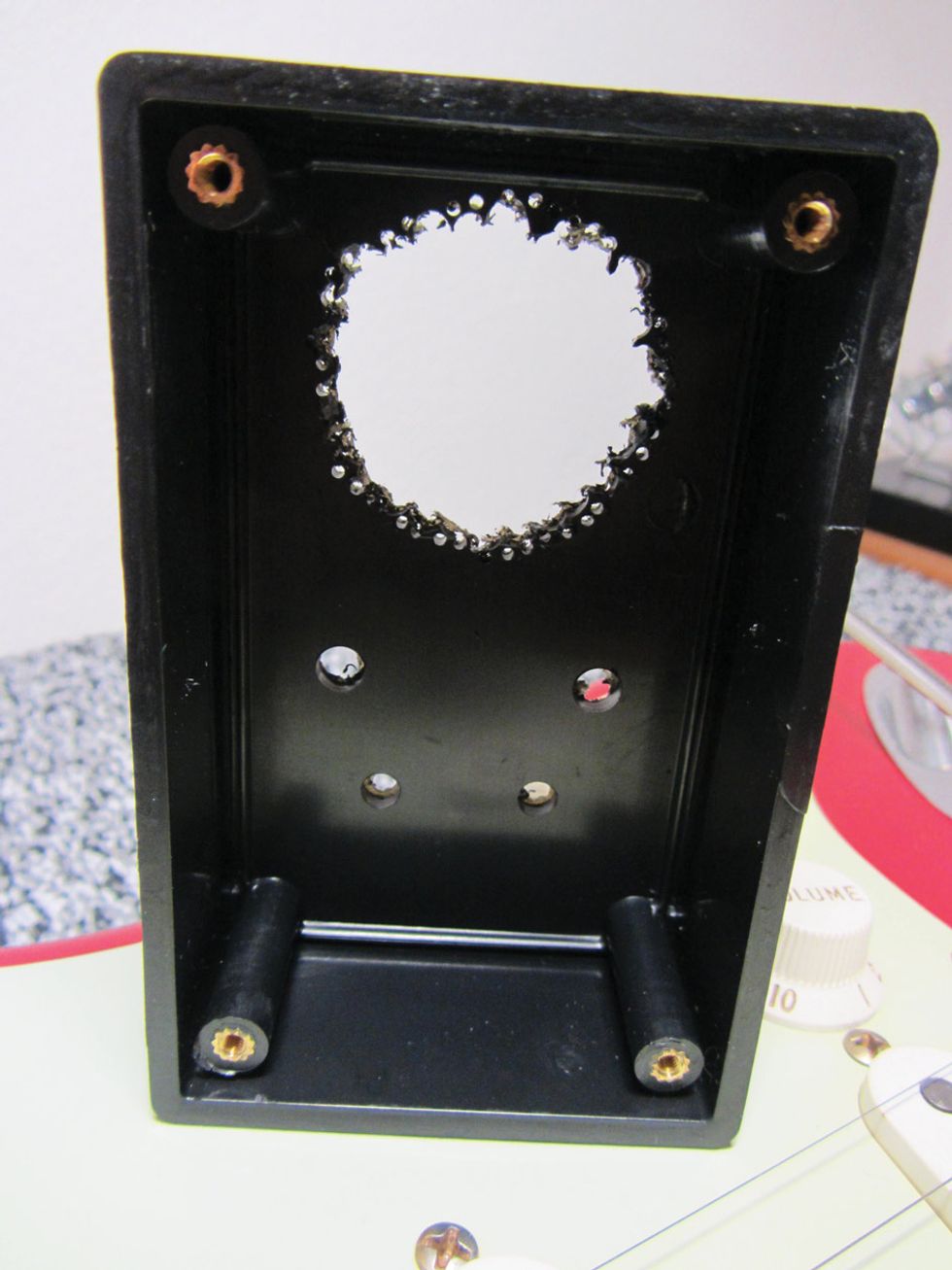
Photo 6 — Courtesy of singlecoil.com
Viewed from the inside, the hole looks ragged (Photo 6), but don't worry—with a half-round file and some sandpaper, you can smooth it out and have it looking quite good in a matter of minutes.
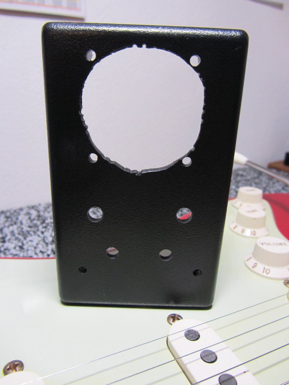
Photo 7 — Courtesy of singlecoil.com
That's one advantage of using a plastic case, rather than a metal enclosure. Photo 7 shows the finished case from the outside.
Next time, we'll mount the meter and wire it up. Until then ... keep on modding!