
This month let's explore Stratocaster wirings that will bring your axe more into the Ritchie Blackmore ballpark. These easy mods are worth trying if you want to get closer to his Strat wiring.
I'm not going to write an essay about all the gear Blackmore has used during his long and outstanding career. The details about his Strats, pickups, amps, and boosters—and let's not forget that magical Aiwa reel-to-reel tape deck—would fill a book. I'll just show you some basic mods to let you explore his pickup configuration. They work with any Stratocaster, no matter the pickups.
For details about the guitars, pickups, amps, and pedals Ritchie has used over the years, I recommend this photo-rich article by Bernd C. Meiser.
There are similarities between all the wirings Ritchie has used over the years. Here are some typical traits:
• He only plays the bridge or neck pickup, but never the two together.
• He never uses the middle pickup, which was lowered so that the pickup cover was flush with the pickguard.
• On some guitars he replaced the unused middle pickup with a dummy coil designed to reduce hum from the single-coil neck and bridge pickups. (I'll explore dummy coils in a future column.)
• His tone pots were rewired for independent control of the bridge and neck pickups.
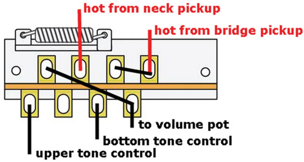
Otherwise, Blackmore's Strats mostly remained stock, so the basic mod is easy. Fig. 1 shows a simplified version of the circuit.
Here's how to wire it up:
- Remove all the wires from the 5-way switch and replace it with a Telecaster-style 3-way switch.
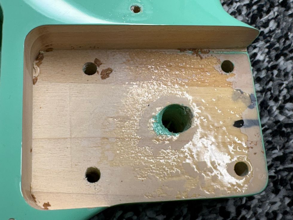
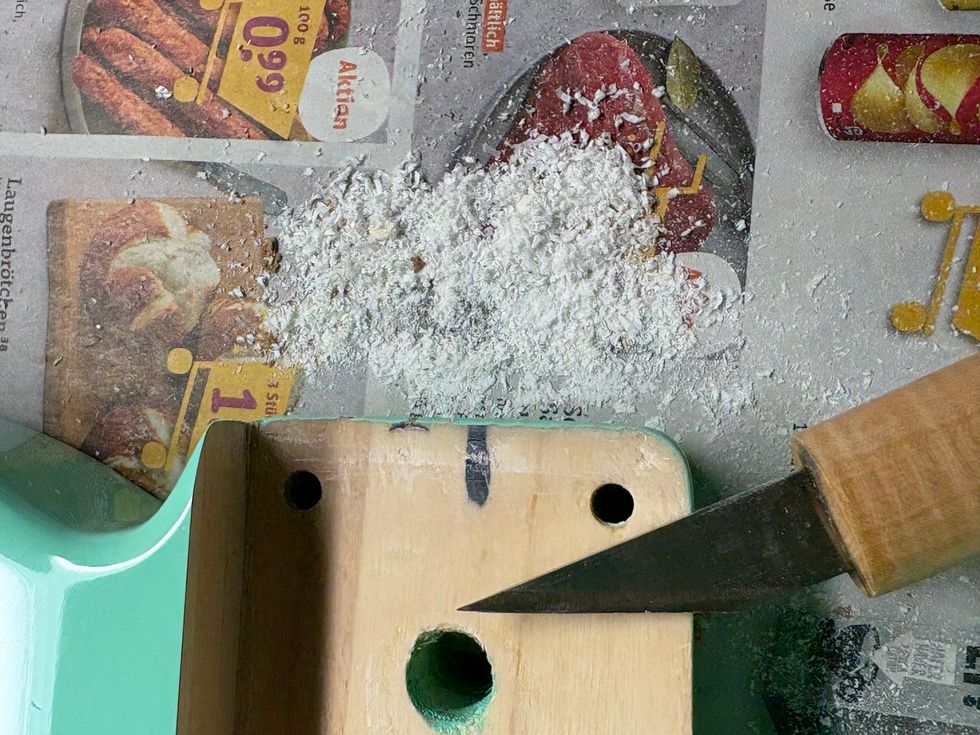
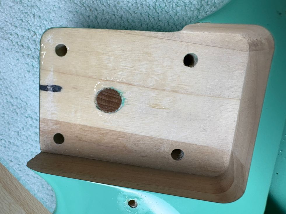
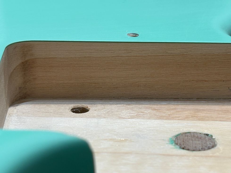
- Remove the middle pickup and install an empty pickup shell to conceal the hole, or leave the pickup where it is, screw it down as low as possible, and cover the bare ends of its wires with electrical tape or heat-shrink tubing.
- Reconnect the wires of the bridge and neck pickups to the new 3-way switch, and solder a jumper wire from the bridge pickup lug to the lug previously used by the middle pickup. (This prevents a dead zone if you accidentally switch to the middle position.)
- Run a jumper from the output of the switch's first stage to the input of its second stage, and from there to the volume pot input.
- Reconnect the tone controls wires. The bottom pot connects to the next lug on stage #2 below the input lug, so it now operates with the bridge pickup. The next lug remains unconnected. The upper tone control connects to the last lug on this stage, where it controls the neck pickup.
That's it! The remaining wiring stays factory stock.
Drilling deeper.
If you want to get a lot closer to Ritchie's classic sound, you need his famous MTC ("master tone circuit") or a replica. John "Dawk" Stillwell, Blackmore's longtime tech, invented this device. He's still in business. (Visit dawksound.com to learn more about him.)
Much has been written about the MTC. Keep in mind that Dawk created it to meet Blackmore's specific needs, so it's designed to suit his equipment. With different amps and stompboxes, the results vary.
The MTC is a so-called LCR network, consisting of an inductor, a cap, and a resistor. But it's a bit more than a basic a LCR network, which is why it isn't a copy of the Bill Lawrence Q-Filter. It combines an LCR network and a treble-bleed network to maintain treble when the volume knob is rolled back. Dawk still sells his MTC, so out of respect for his work I won't dissect the circuit any further. Whether to buy an MTC or get a faithful replica is your decision.
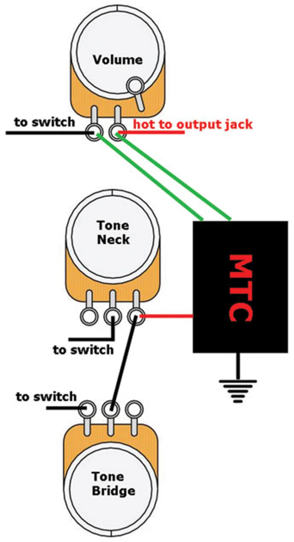
If you decide you need one of these puppies, installation is easy. The new 3-way wiring stays untouched. Simply remove the tone cap from the circuit and keep the wire connecting the tone pots as it is. Next, connect the MTC's four wires as shown in Fig. 2. The two green wires from the treble-bleed network are connected to the volume pot's input and output. (It doesn't matter which green wire goes where.) The black and red wires are for the tone control. The black connects to ground and the red connects to the tone pots.
Okay, we're done! I hope you have fun with this project. I'll have another for you next time, so until then ... keep on modding!
[Updated 9/24/21]