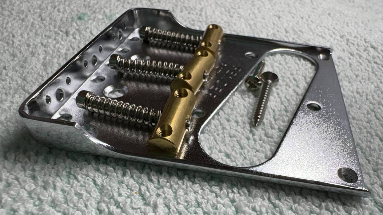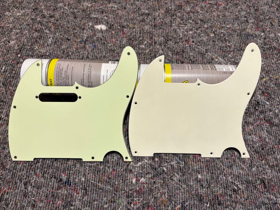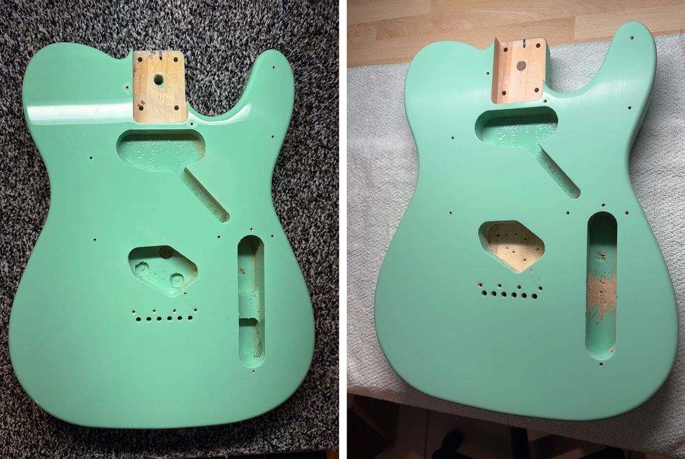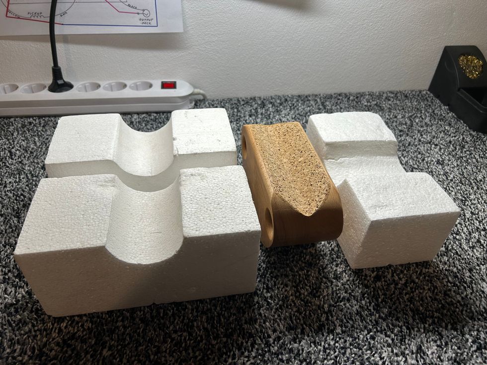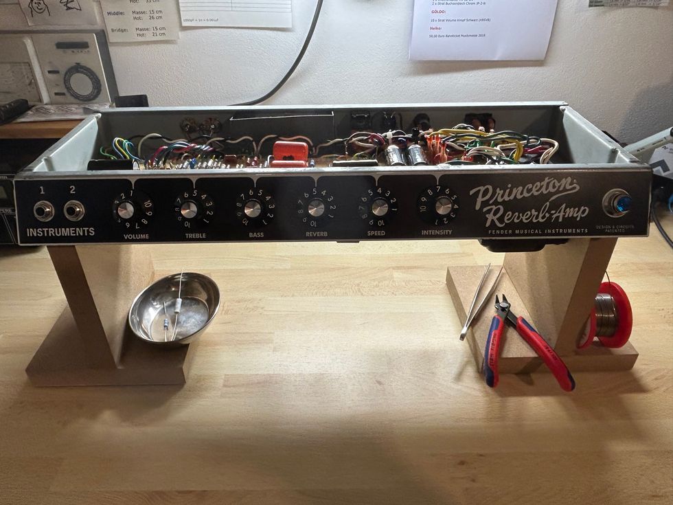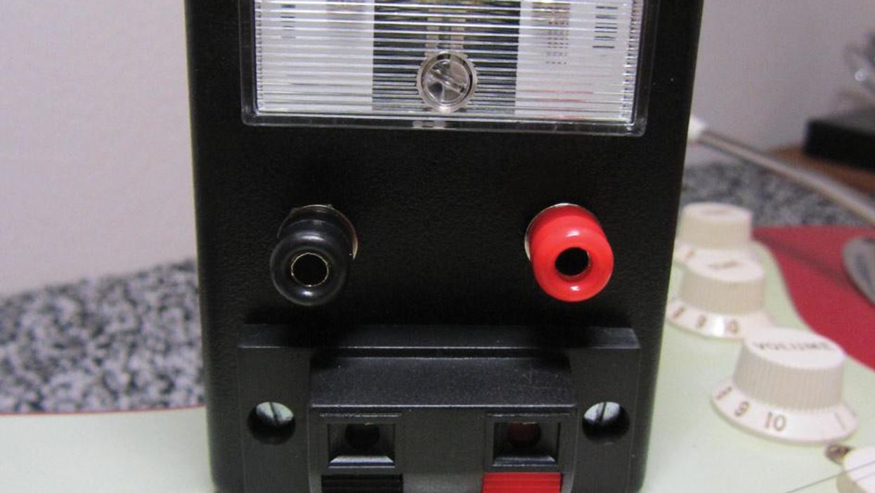

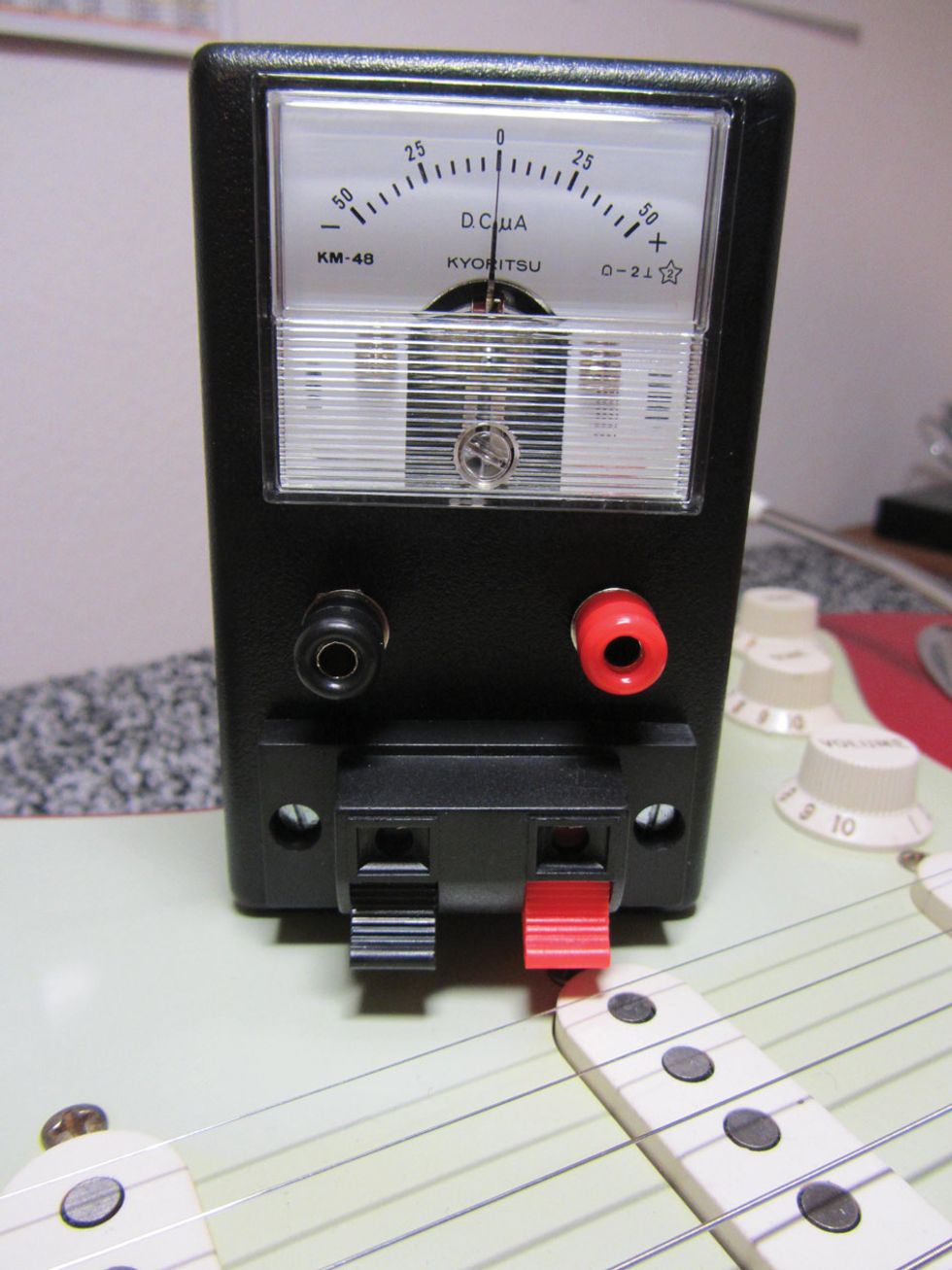
Photo 1 — Photo courtesy of singlecoil.com
When modding an electric guitar, one of the most common projects a player might tackle is replacing stock pickups with aftermarket units. Ever since the '70s, when replacement pickups became readily available, we've come to understand that instead of buying another instrument, we can alter the tone and response of one we own for a lot less money. The technical aspects of a pickup swap aren't too daunting, and it requires only hand tools and soldering gear.
But as anyone who's a regular reader of Mod Garage knows, a seemingly simple project can become a nightmare if the pickups you drop into your beloved 6-string are out of phase with each other. To avoid this vexing problem, you need a handy-dandy pickup phase tester.
the pickup's hot wire.
Too bad they don't exist—at least I've never come across a commercial device dedicated to this job. But hey! That simply gives us an incentive to build one. It's inexpensive and it will help you avoid out-of-phase issues that might ruin your day.
We started this project in my previous column (“Build a Pickup Phase Tester, Part 1"). If you haven't read this yet, check it out before going any further.
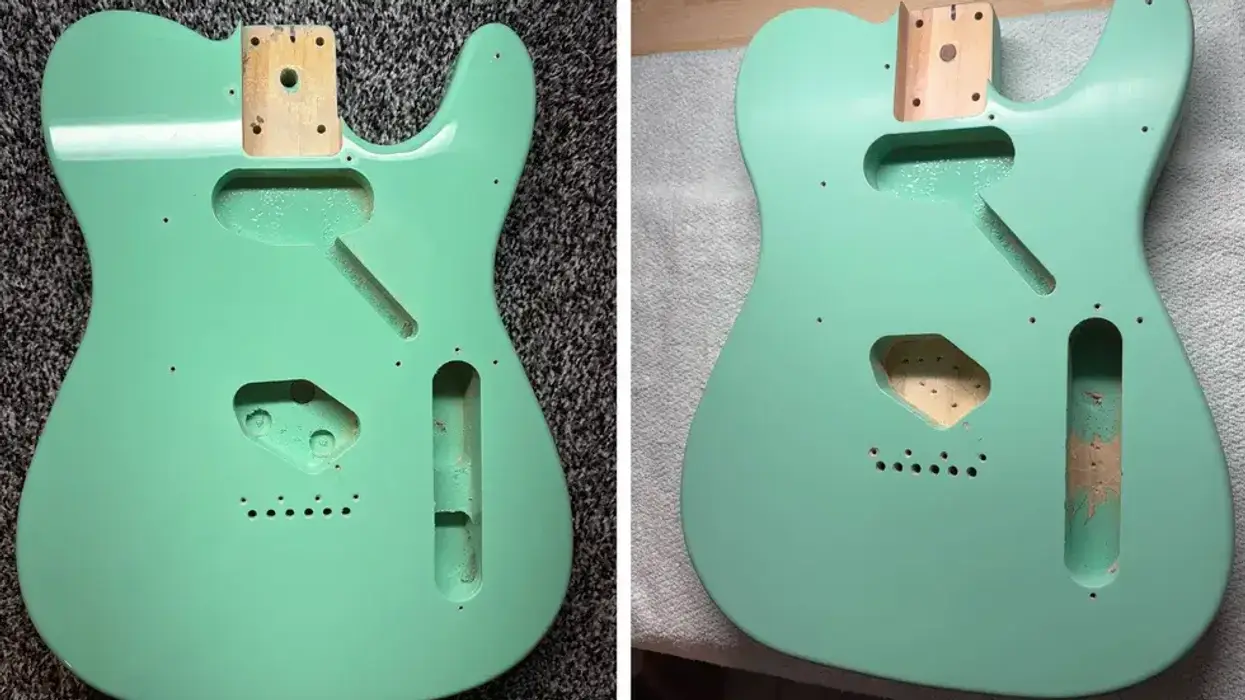
Okay, let's resume where we left off. After installing and mounting the parts, as described in Part 1, we now have a unit that looks pretty good (Photo 1), at least from the front.
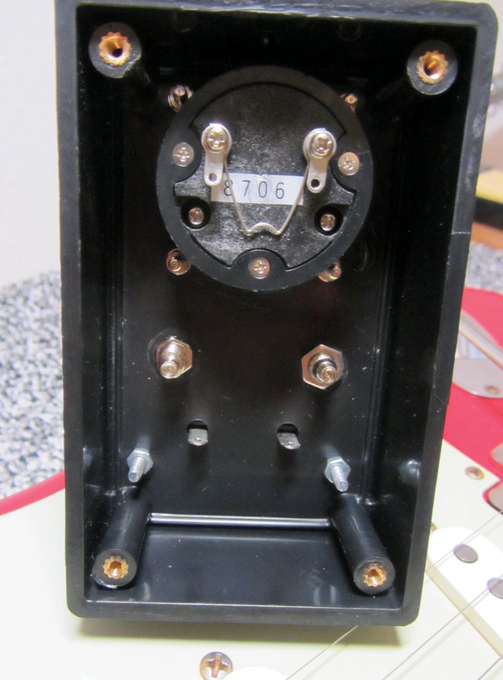
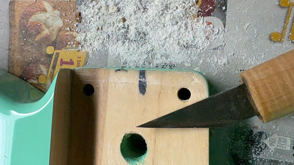
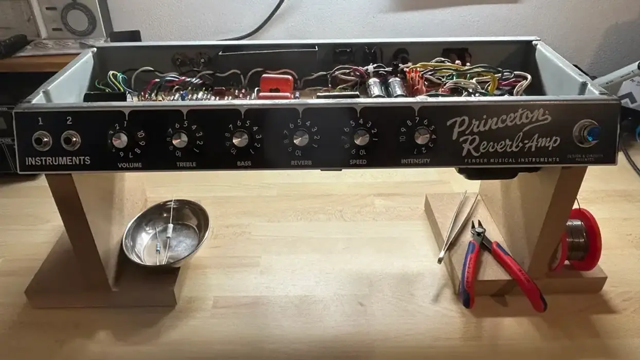
Photo 2 — Photo courtesy of singlecoil.com
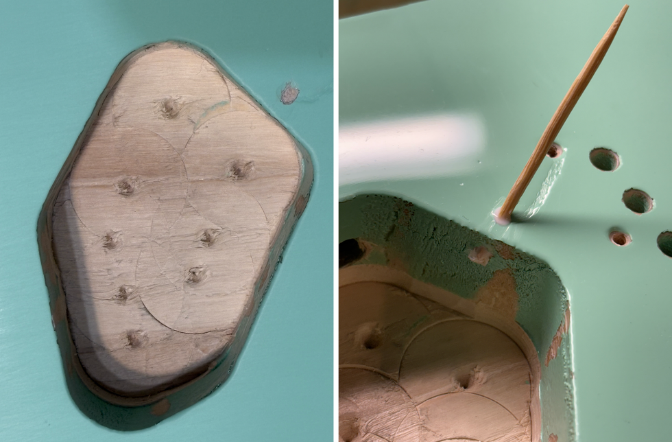
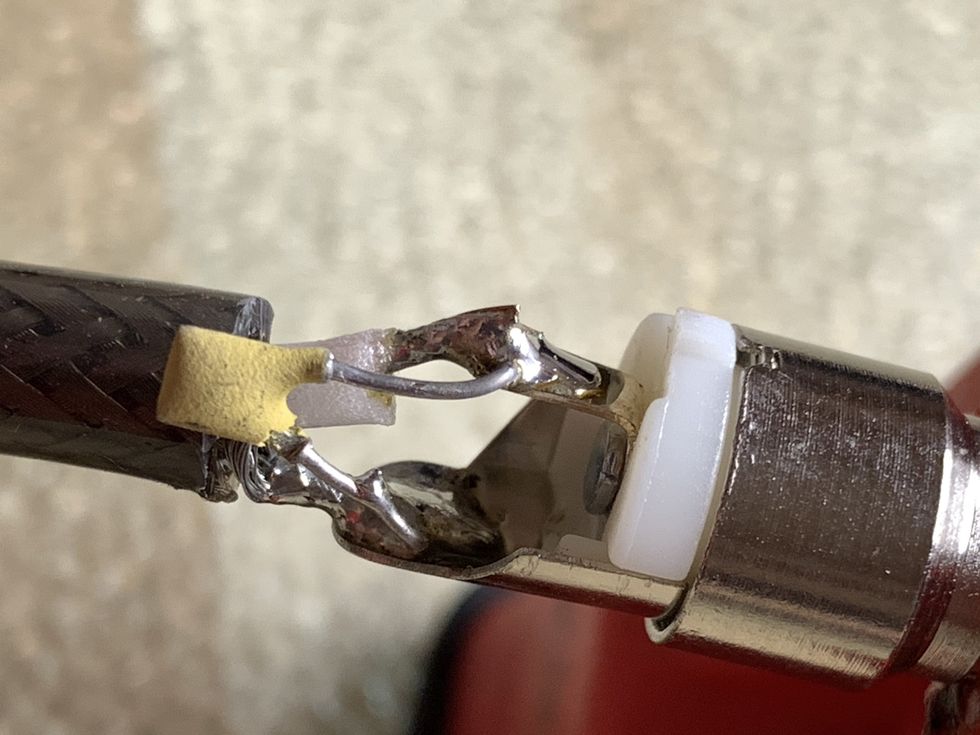
The next step is to study the inside (Photo 2) and then wire this meter up. This isn't hard because both input stages are wired in parallel. To make it even easier, I took our red and black wires and cut them in two to make miniature Y-cords (Photo 3).
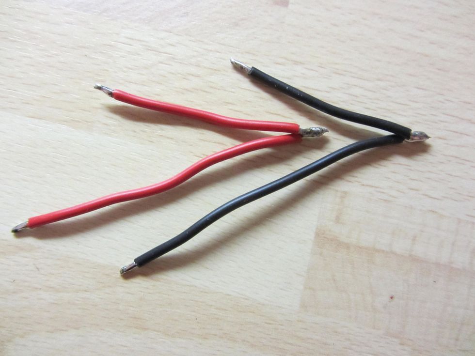
Photo 3 — Photo courtesy of singlecoil.com
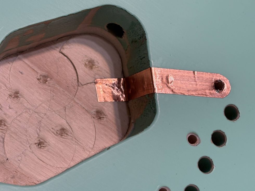
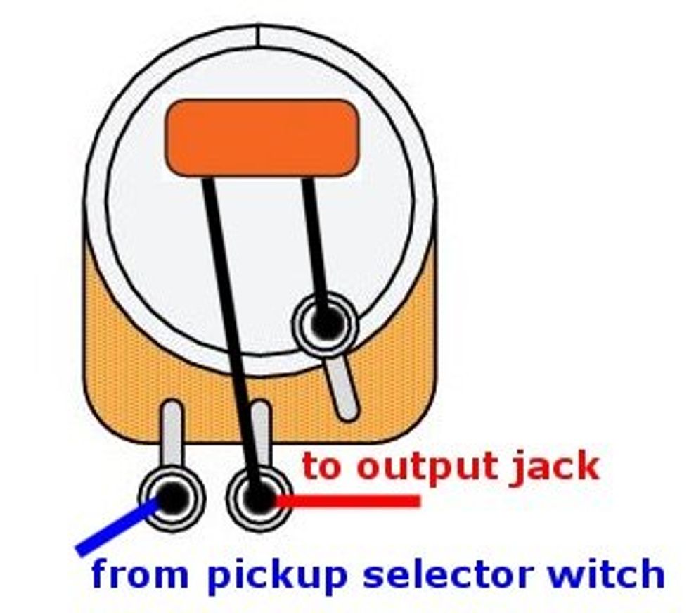
Here's the signal path, as shown in Photo 4:
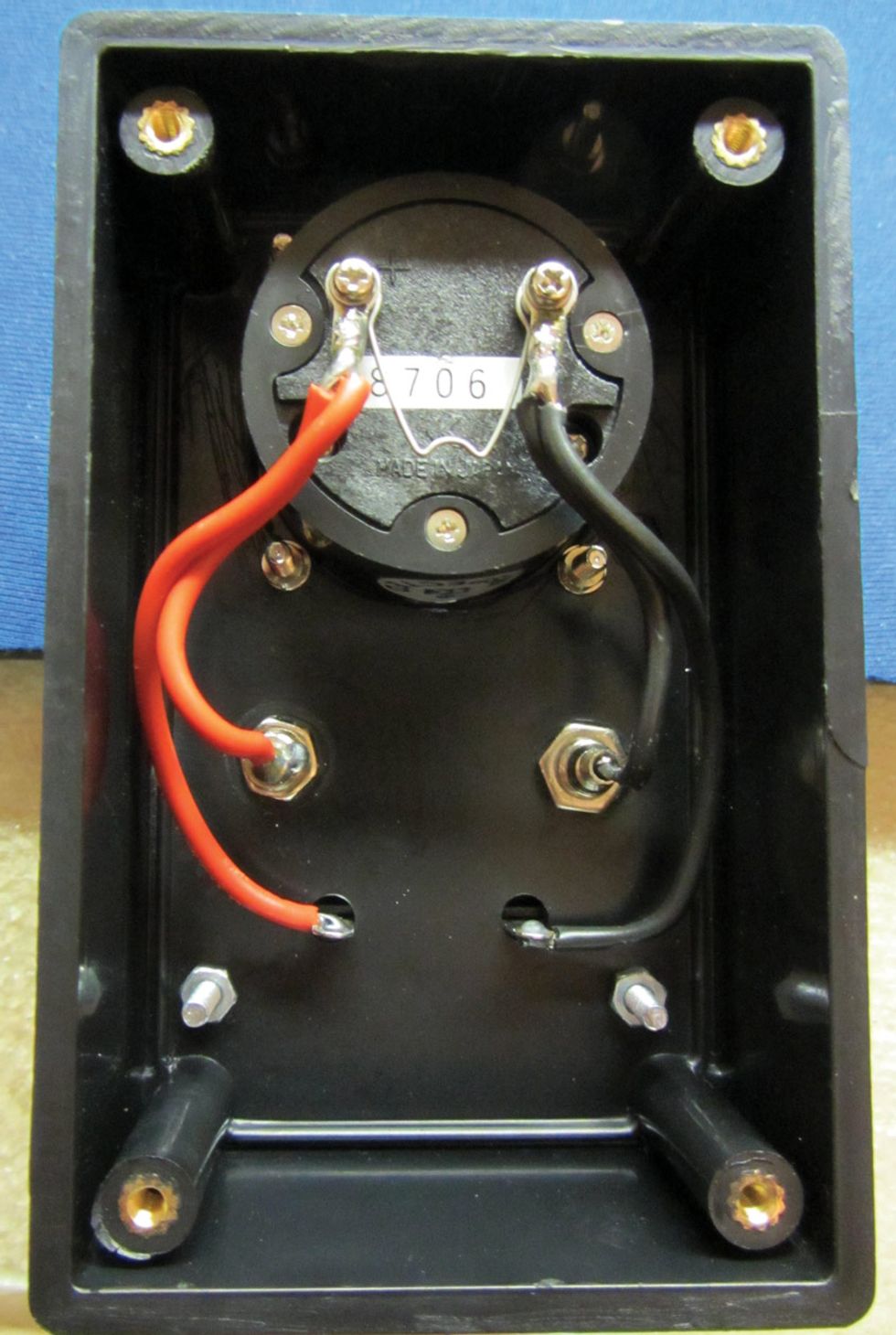
Photo 4 — Photo courtesy of singlecoil.com
• The meter's plus terminal connects to the red banana input jack and the red clamp of the speaker terminal.
• The meter's minus terminal connects to the black banana input jack and the black clamp of the speaker terminal.
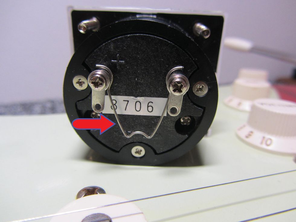
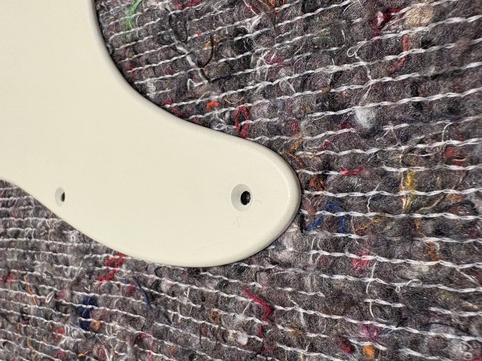
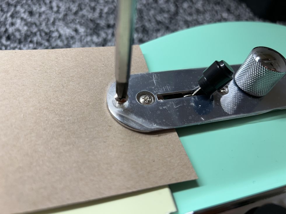
Photo 5 — Photo courtesy of singlecoil.com
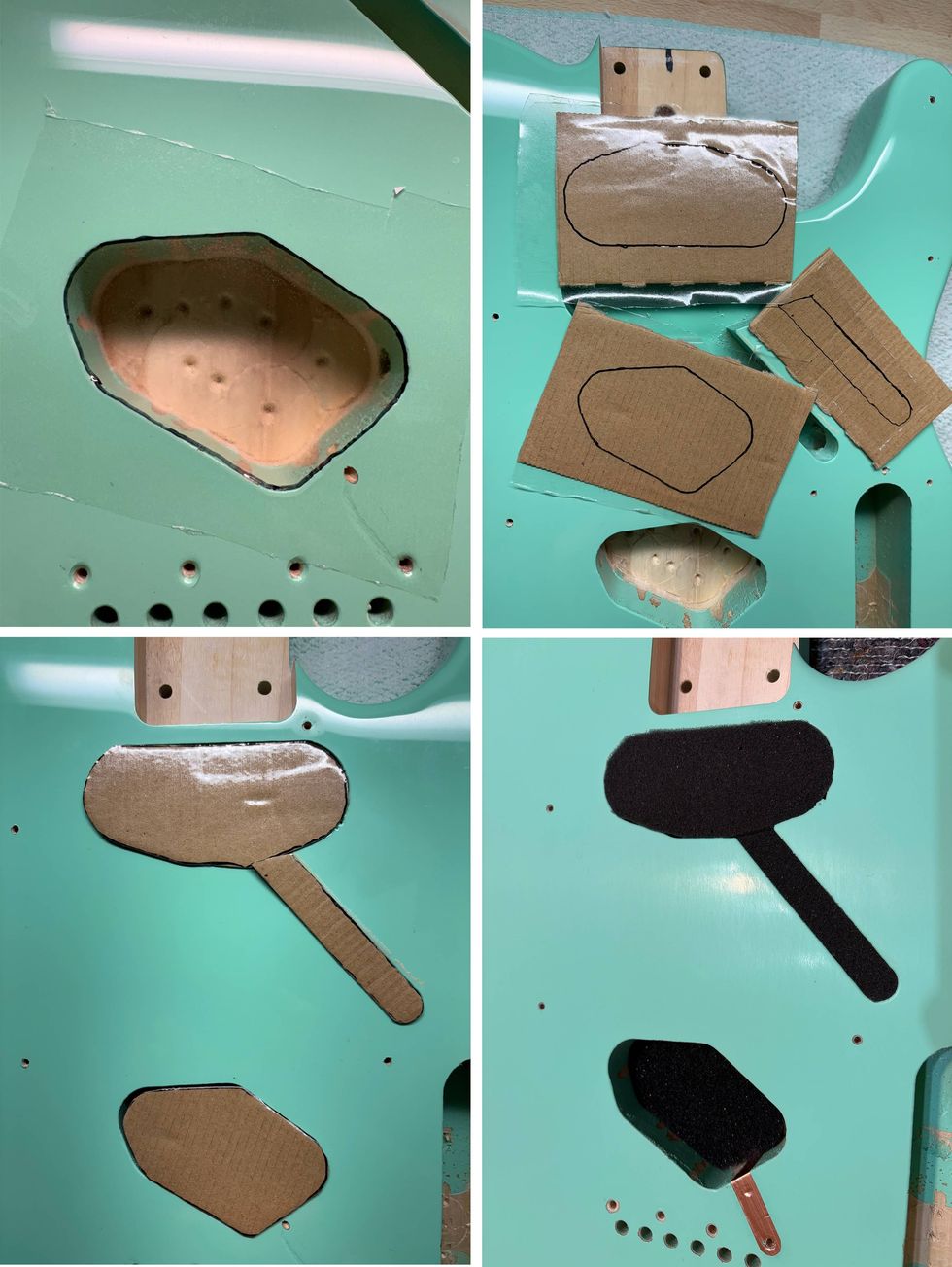
After you've soldered the wires to their respective points, there's one last important step to take before closing the case. On most analog meters, you'll find a tiny metal spring between the plus and minus terminals, as indicated by the red arrow in Photo 5. You need to remove this spring to allow the meter to work as intended.
So what's the spring doing there? It's a transportation lock designed to protect the very sensitive measuring mechanism during the shipping process. (In case you're curious, this little spring is called an “eddy current brake." It works like a jumper wire, causing a short circuit in the meter. This short circuit establishes an eddy current that dampens the measuring mechanism and makes the needle rest in the zero-center position.)
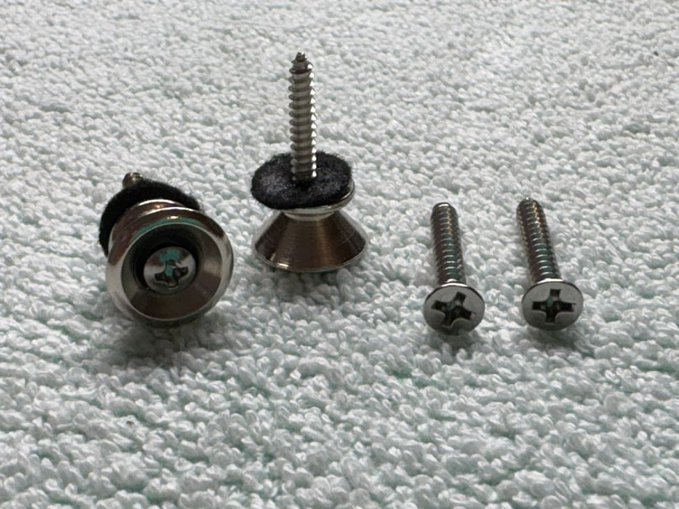
Okay, once you've removed the spring, assemble the case, install the rubber feet, and go find a pickup so you can test out your new meter.
Check, check—one, two. Here's how to connect the pickup wires to the meter: The white (hot) wire goes to the plus (+) and the black (ground) wire goes to the minus (-).
Note: For this test, it's important to connect the wires exactly like this. If a given pickup's wires have different colors, simply follow the color scheme that indicates hot and ground as defined by the manufacturer.
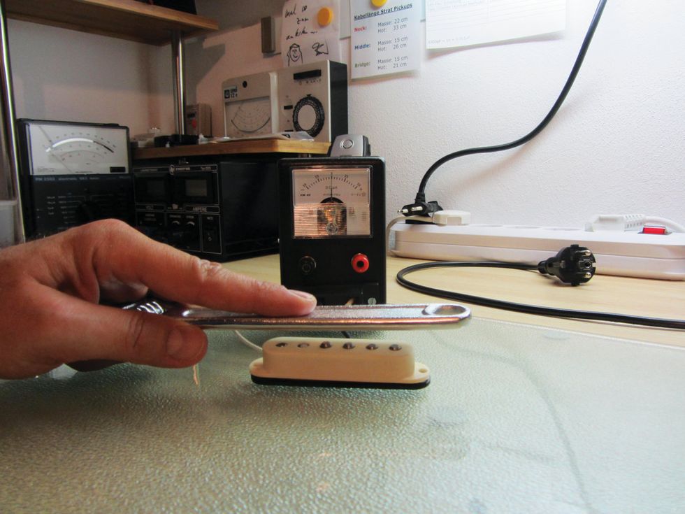
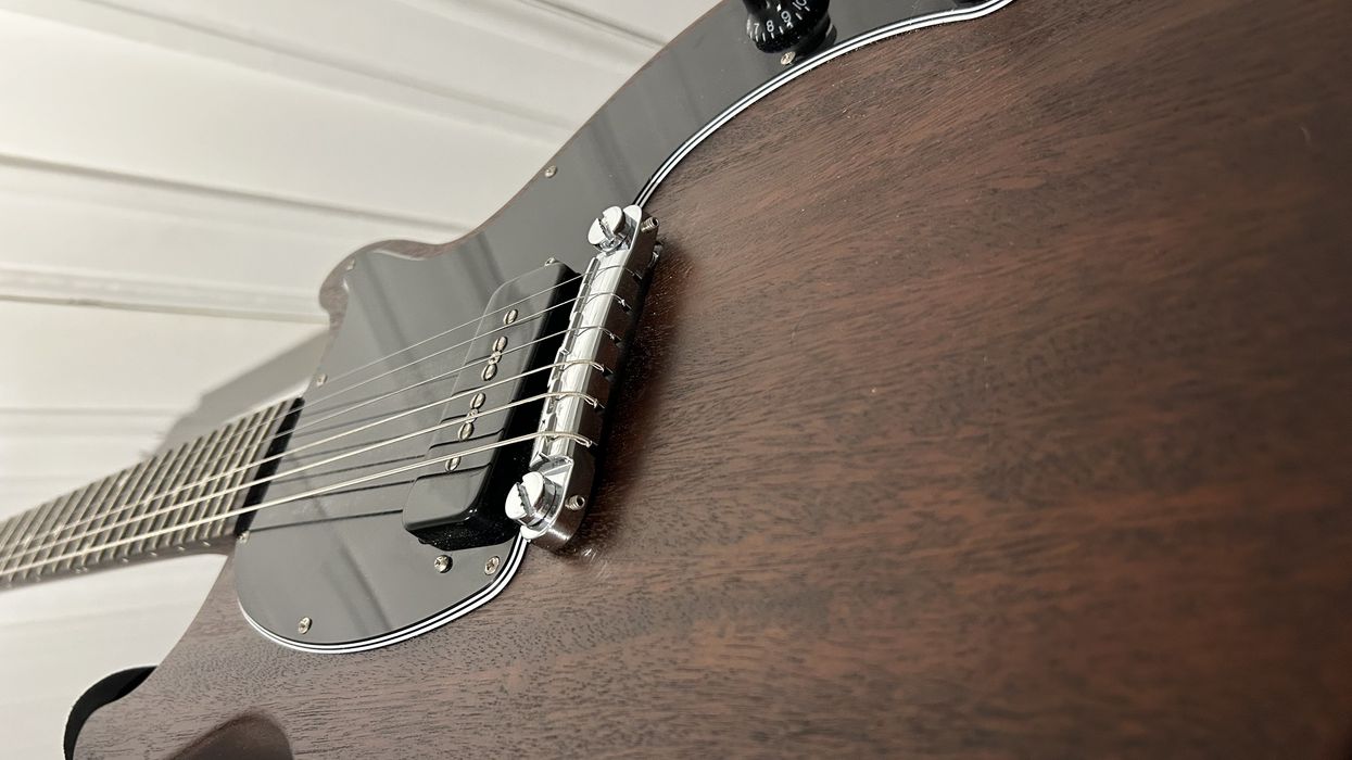
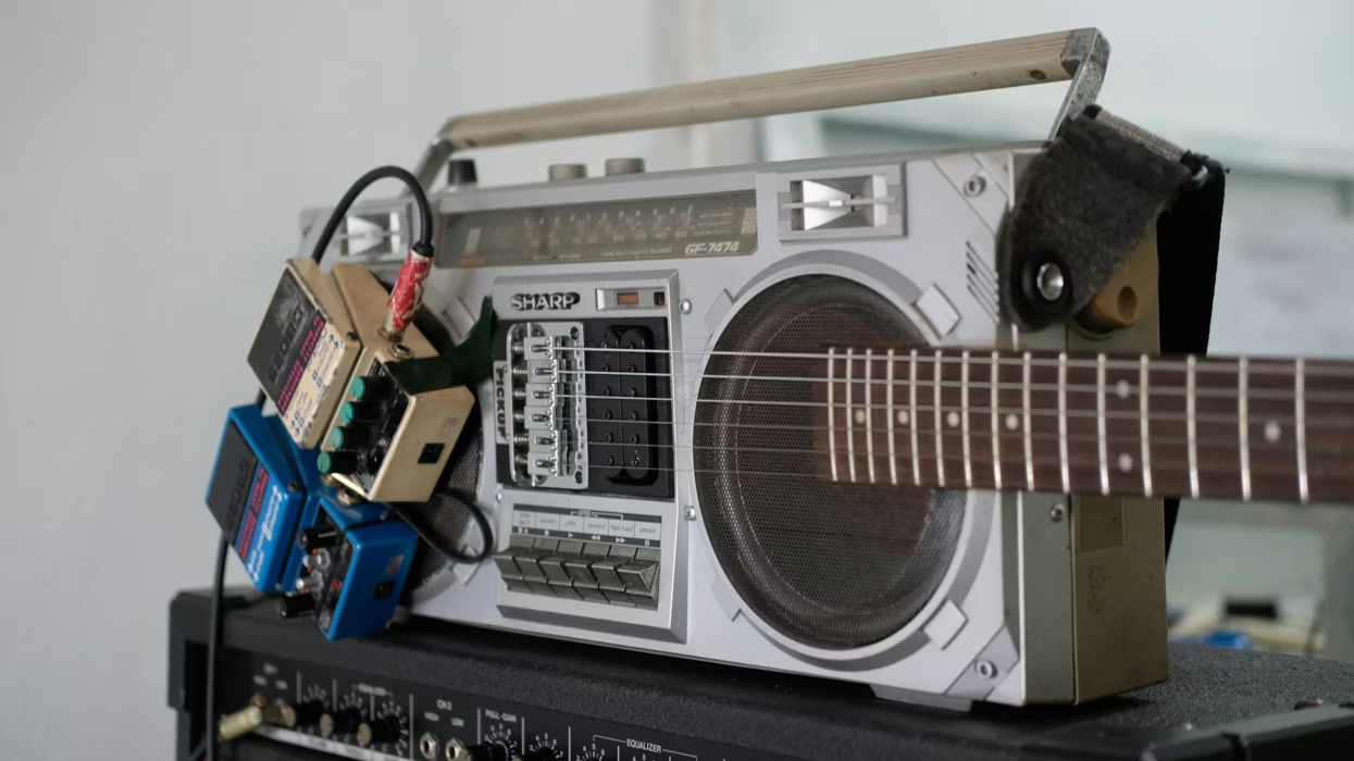
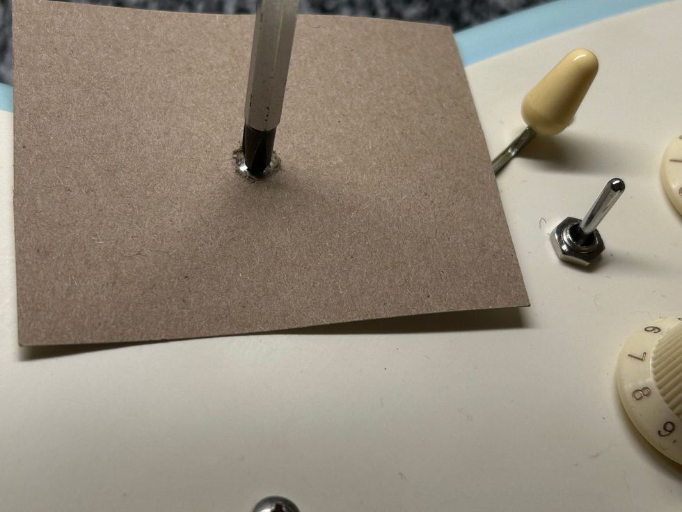
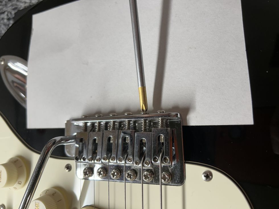
Photo 6 — Photo courtesy of singlecoil.com
Next, take a big screwdriver, wrench, or a piece of steel or iron and slowly bring it toward the pickup's pole pieces (Photo 6). If the phase-testing unit's needle starts moving toward the plus (+) range of the scale, this means the wire that's connected to the plus input jack is the pickup's hot connection. If the needle starts moving toward the minus (-) range, this means that the pickup wire connected to the plus input jack is the ground.
You'll be surprised how many times the white wire is not really the pickup's hot wire. Why is this? Even though it's common to identify a pickup's white wire as positive and the black wire as negative, that doesn't take into account the pickup's magnetic polarity. Because of this, to avoid an out-of-phase nightmare when combining several pickups—particularly when they're from different manufacturers—it's always best to check each unit with your meter and make note of the hot and ground wires.
Congratulations—you've built your own phase-testing unit! Next month, we'll dive into our next project, which involves humbuckers. Until then ... keep on modding!