
Over the years I've been writing Mod Garage, I've received requests to explore wirings created by the late guitarist, luthier, session musician, and boy genius, Daniel “Dan" Kent Armstrong, who, sadly, passed away in 2004. If you're unfamiliar with his legacy, I suggest you take a moment to check him out here. Let's start with his most famous wiring scheme: the original Armstrong “super-strat" wiring. Some of you may know this wiring. It was very common during the whole “super-strat" era of the '80s and early '90s, and it's still a landmark today.
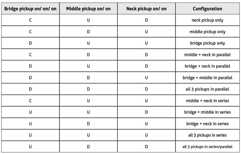
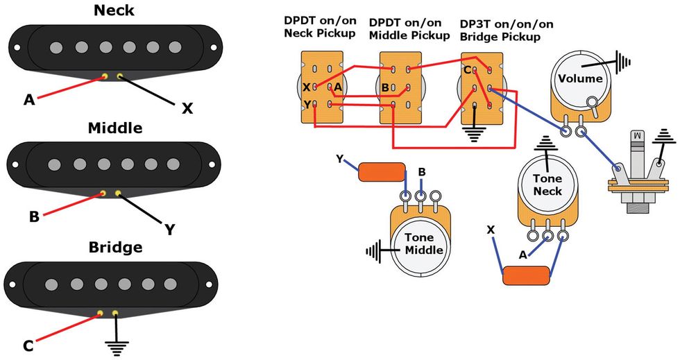
The basic idea is simple: You replace the standard 5-way switch with three individual toggle switches—one for each of the three pickups—to coax as many different sounds as possible from one guitar. Though the concept wasn't new, Armstrong gave it a twist. Instead of using three simple SPDT on/off switches, he used two DPDT on/on switches for the neck and middle pickups, plus a DP3T on/on/on switch for the bridge pickup. This let him access both series and parallel switching for multiple pickup combinations, and thus extract 12 different tones from a standard Stratocaster.
All the pickup combinations are in phase, so if you're looking for out-of-phase tones, this arrangement may not be your cup of tea—at least not without some mods to yield these additional sounds. Armstrong's circuit works on all guitars with three pickups, including those with humbuckers.
For this configuration, we're using stock Stratocaster tone controls: the middle and neck pickups each have an individual tone pot, while the bridge pickup has none. However, you can further enhance the wiring's sonic flexibility by putting different cap values on each tone control— something I'll elaborate on in a moment.
The switching matrix. The chart below shows the different combinations offered by this wiring. Here's how to interpret the letters: U means the switch is in the up position, D stands for down, and C indicates the bridge pickup's 3-way on/on/on switch is in the center position.
This wiring's switching matrix is challenging to operate, and you'll need some time to get familiar with the three switches and how they work together. I know I couldn't play a guitar wired this way onstage without a printed operation manual describing all the different possibilities, but if you want to squeeze as many sounds as possible out of a Strat, this is your ticket. This is a complex circuit that requires solid soldering and wiring skills, and isn't a beginner's project.
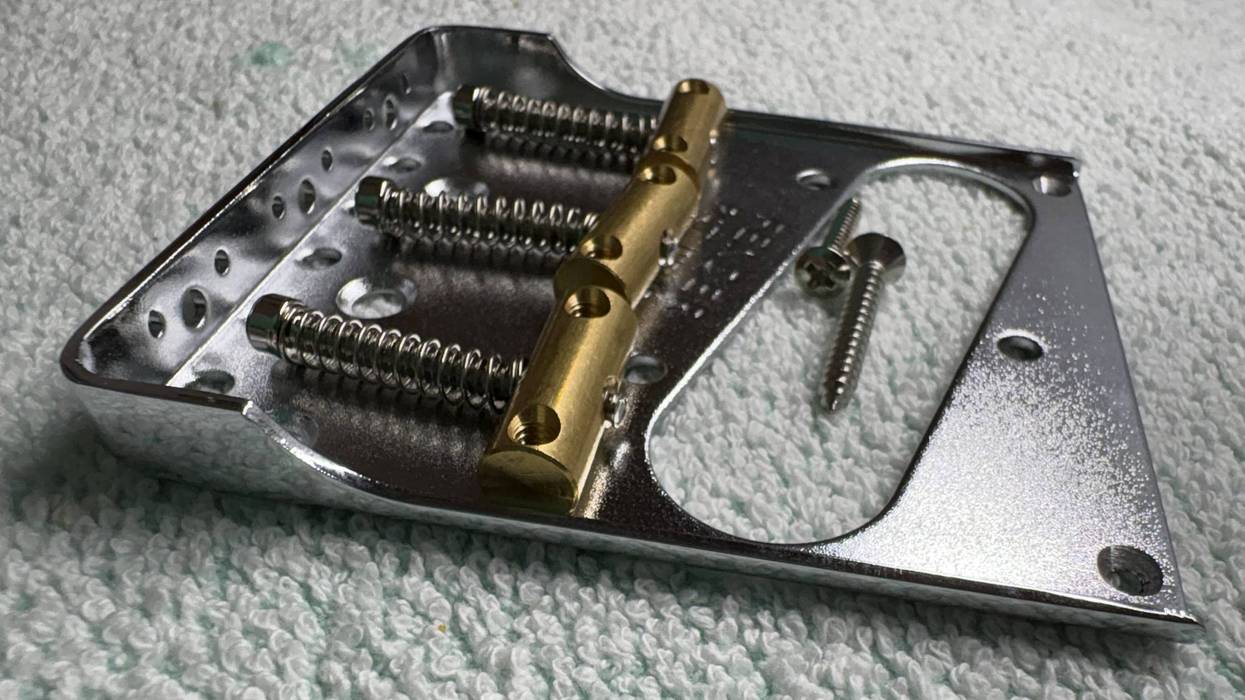
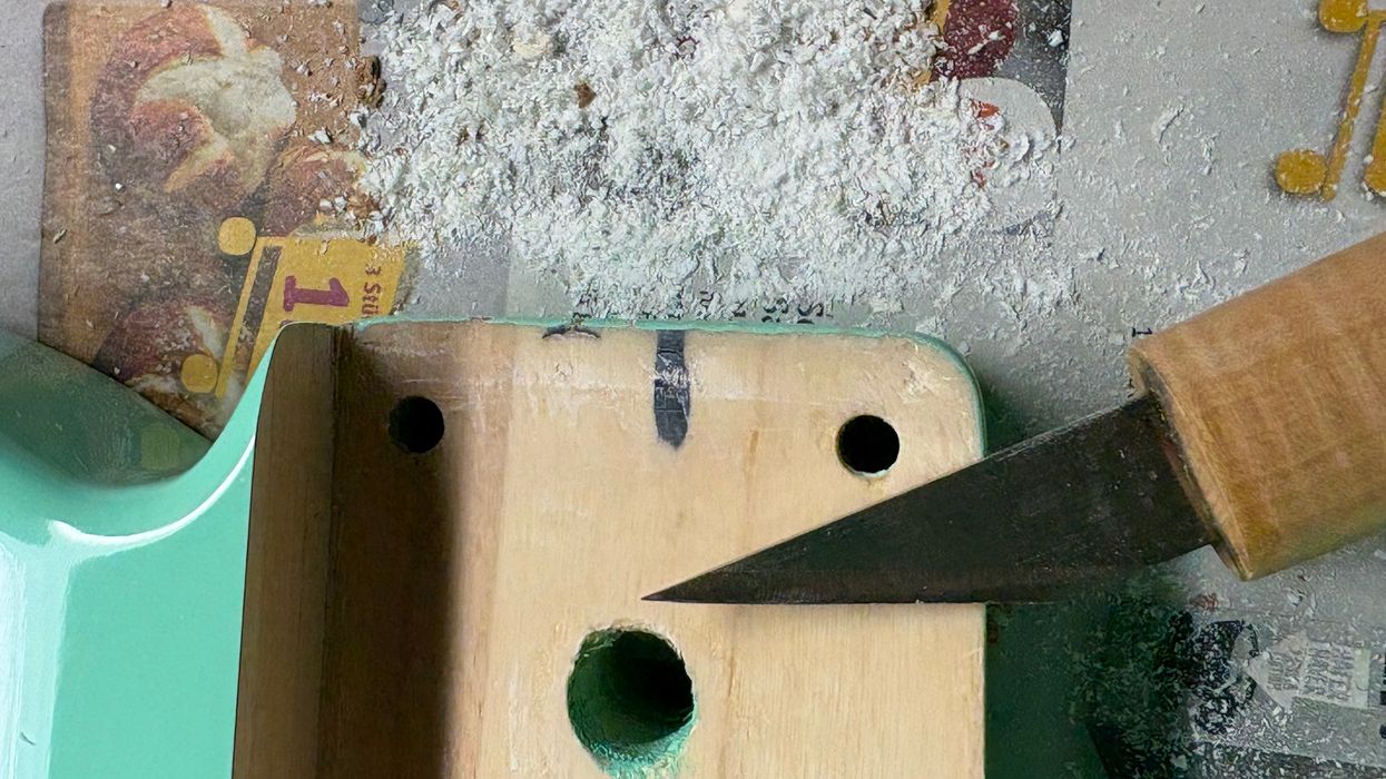
The shopping list. You can use your stock Stratocaster pickguard for this mod. Simply remove the 5-way switch and drill three holes to install the switches where the 5-way switch was previously located. Of course, the slit that housed the original 5-way switch will be visible between the three new switches. If that doesn't seem appealing, buy a new pickguard that's not pre-drilled for the standard 5-way switch. This will look much cleaner.
Other than that, you only need a pair of 2-position DPDT on/on switches (for the middle and neck pickups), a single 3-position DP3T on/on/on switch (for the bridge pickup), and some wire. Rather than trying to save a few pennies on inferior budget switches, be sure to use high-quality units. Poorly constructed imports won't last long, and they produce all kinds of electronic and mechanical noise when you're operating them.
The wiring. Again, this isn't a beginner's project, so if you feel unsure about tackling such a complex circuit, I suggest hiring a pro to do this job for you—or at least starting with an easier mod to gain some experience.
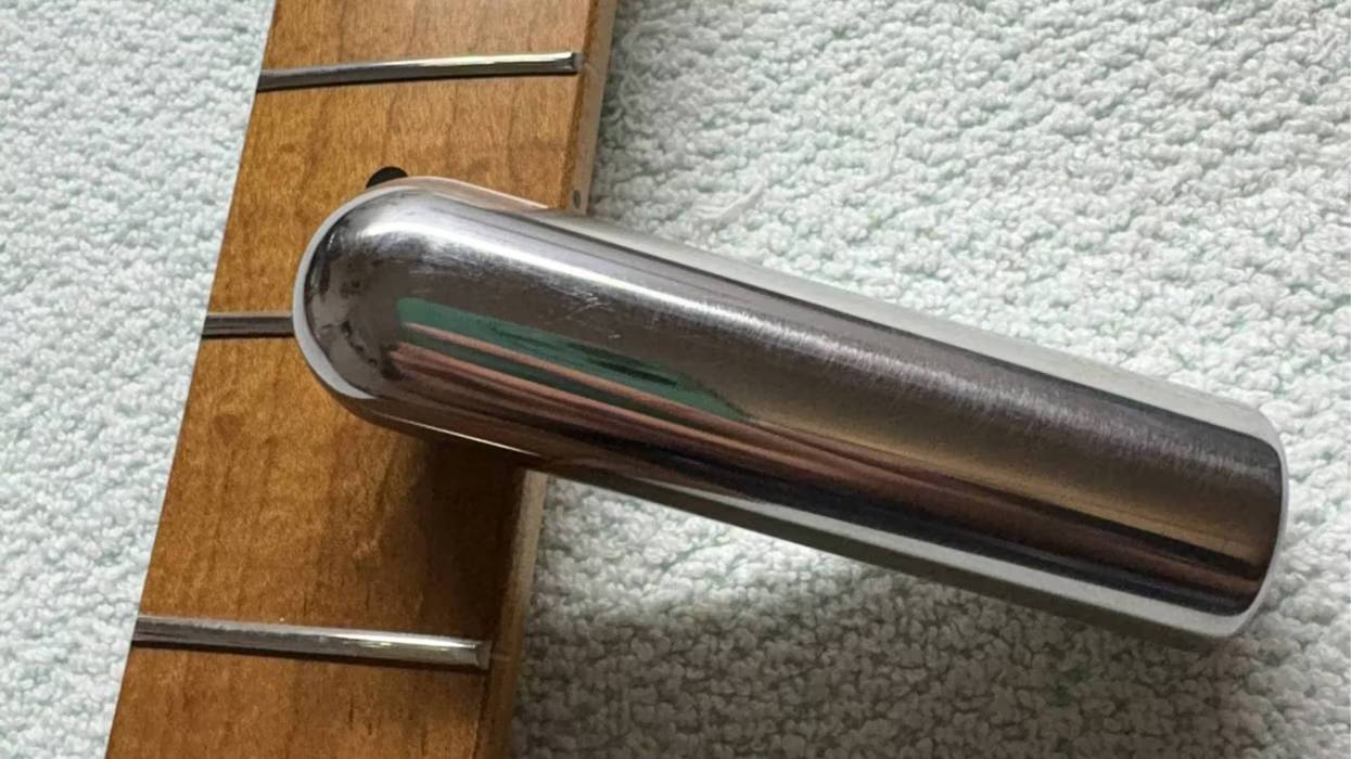
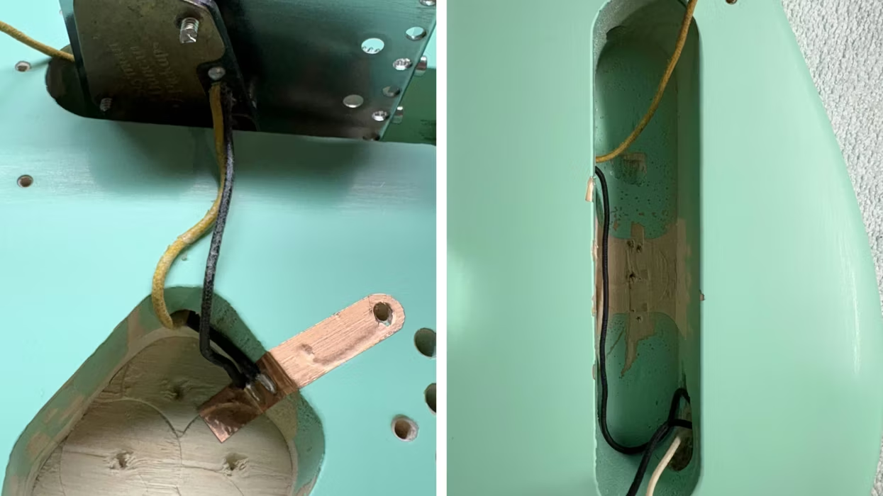
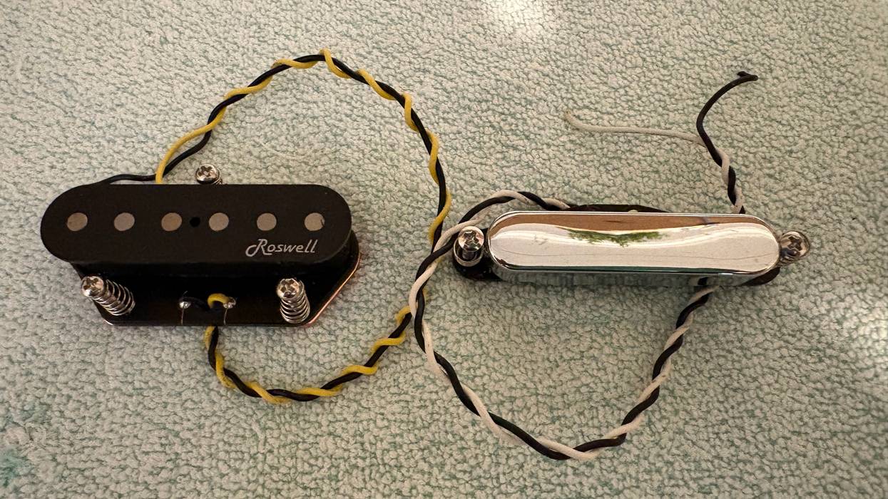
If your pickups have a metal baseplate (like a Telecaster bridge pickup) and/or a metal cover (like a Telecaster neck pickup or a humbucker) that's connected to the pickup's ground, you need to break this connection and solder a new, dedicated ground wire to the metal part. If you don't do this, your pickups will produce all kinds of weird noises in series mode.
For this wiring, it's also important to connect the case for each of the three switches to ground. Depending on its design, the switch may have a solder tab for this. If not, you'll have to wrap a wire around the threaded part of the switch's bushing and solder it to ground on the other end.
Dan Armstrong's classic “super-strat" wiring yields 12 sounds from a standard 3-pickup Fender Strat.
Armstrong's original schematic has an additional 0.05 µF capacitor connected between the volume pot case and the wire coming from the tremolo claw. This wire grounds the strings when you touch them, and the 0.05 µF capacitor is meant to protect you from electrical shocks. This cap is optional—you can get all the circuit's switching functionality without it. In my opinion, a 0.05 µF cap isn't a good choice to prevent electrical shocks. For this task, I prefer a 0.001 µF (1 nF) cap with a minimum rating of 500 volts wired in parallel with a 220k resistor.
In the original wiring, Armstrong chose a 0.01 µF value for both tone caps, but feel free to use whatever value you prefer. Also, it's not a crime to use different values for each tone pot. For example, you could experiment with a 0.01 µF for the middle and a 6800 pF for the neck pickup. Because of the many wires in this circuit, I decided to follow Armstrong's original approach for drawing the schematic. With all those wires crossing each other, a typical schematic looks way too confusing.
That's it! We'll revisit this wiring in a future installment to implement some nice mods. But next time, we'll return to 4-conductor humbuckers and I'll show you how to determine which wire goes where, if you don't have the color-code scheme for the individual wires. And we'll do this without buying super-expensive gizmos like a pickup analyzer or a digital scope. Until then ... keep on modding!