Hello Jeff,
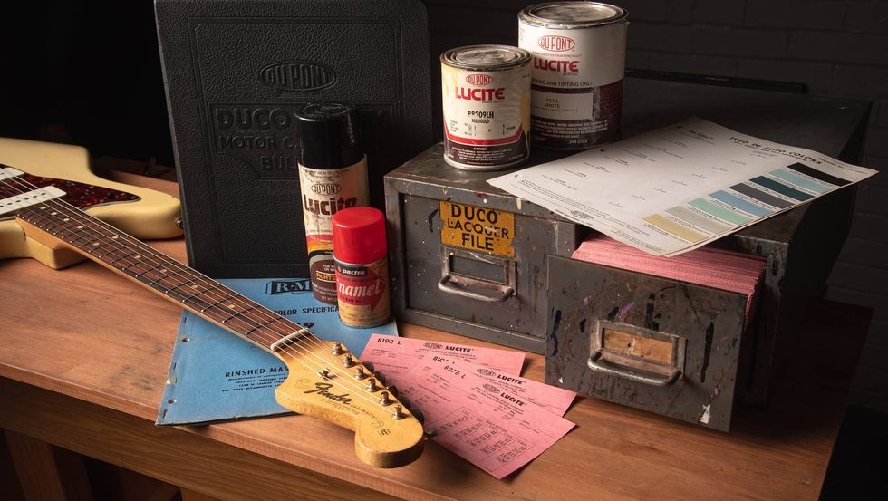
I acquired a Fender Custom Vibrolux Reverb I wasn’t happy with (Photo 1). It had a printed circuit board, the reverb wasn’t great, and it didn’t have the tone I was looking for. So I ripped out the printed circuit board and installed point-to-point eyelet board (Photo 2). In the tone stack, I know the mid .47 µF capacitor can make the bass a little muddy. I looked at a lot of schematics and learned that the Super Reverb uses a .22 µF. I decided to go with a .33 µF for channel 1 and channel 2 so I could be in the middle and clean up the bass tone. I also added an extra potentiometer for channel 2 in case I wanted to scoop some mids.
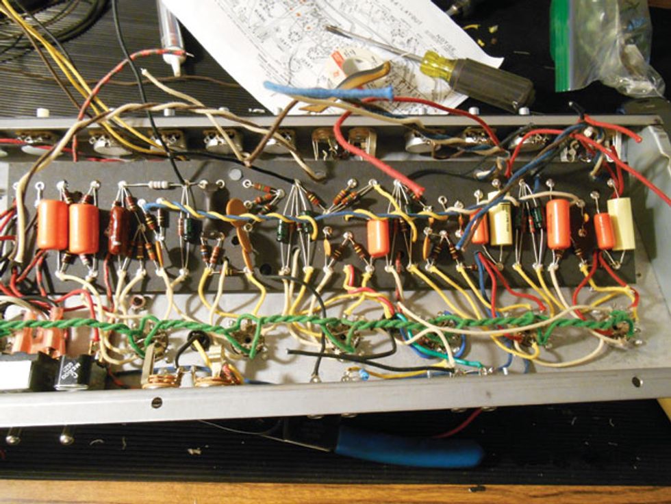
Photo 2
Then I installed a new Classic Tone reverb transformer and output transformer. My power transformer is stock, and I’m still deciding whether to change it. I know this one has more voltage, which gives it a tighter, beefier tone. If I went with an original-spec power transformer, that would mean lower voltage, but more mids and earlier break-up, right?
I also have a question about the reverb capacitor: In many photographs I see that Fender used a ceramic disc for the reverb coupler. I used an Orange Drop. Is this okay or should I go with ceramic?
Thank you,
James Castillo
Hi James,
I’m glad to hear you’ve made such great progress with your amp, and I’ll try to answer your few remaining questions. I’ll also include suggestions for other readers (who may not be planning to replace their circuit boards) to bring their Custom Vibrolux Reverbs closer to the original. (Note: These suggestions are applicable to most Custom-series amps, but not the new ’68 Customs.)
You mentioned you replaced the reverb and output transformers, which surely improved the amp’s tone. But you were on the fence about replacing the mains (power) transformer. Comparing the schematics for the original and the Custom confirms that the Custom’s voltages are higher. This, of course, can change the amp’s sound, since higher voltages can make an amp tighter and possibly brighter. My suggestion will let you keep the tightness and power of the output stage, but provide a bit more warmth and compression.
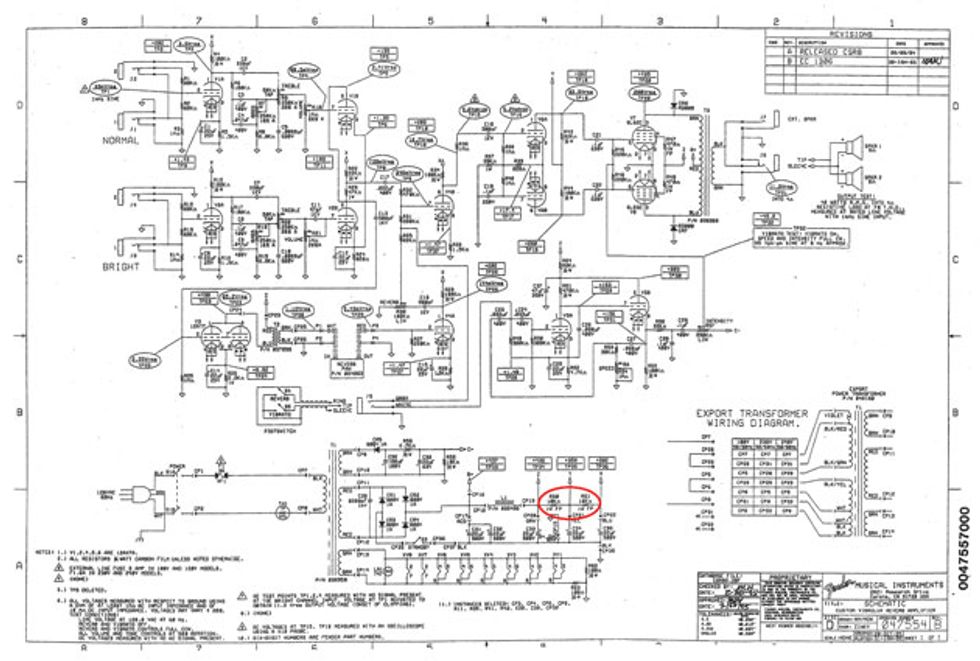
Fig. 1
Leave the stock transformer and instead change the value of the resistors in the power supply. In Fig. 1, R60 and R61 are circled in red. I suggest increasing the value of R60 so that the B+ at point Y drops to approximately 310 VDC. Start with a 20k 1W resistor and check the result. If it’s too far off, increase or decrease the value.
Once you have that close, measure the voltage at point X in the power supply. Ideally, you want approximately 260 VDC, so raise or lower this value accordingly. Now you’re much closer to having the sound and feel of a vintage front end with extra kick in the output stage!
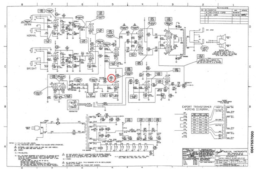
Fig. 2
You also asked about a ceramic versus an Orange Drop (poly) cap in the reverb circuit. In Fender-style amps I prefer to keep ceramic caps where they originally existed, as I think they have a bit more sparkle—an important trait to retain in these amps. While the reverb input cap is a 500 pF in both the original and the reissue, the original reverb output signal cap is a .003 µF (3000 µF), but the reissue uses another 500 pF cap (Fig. 2). I’d install the original value and see if that improves your reverb.
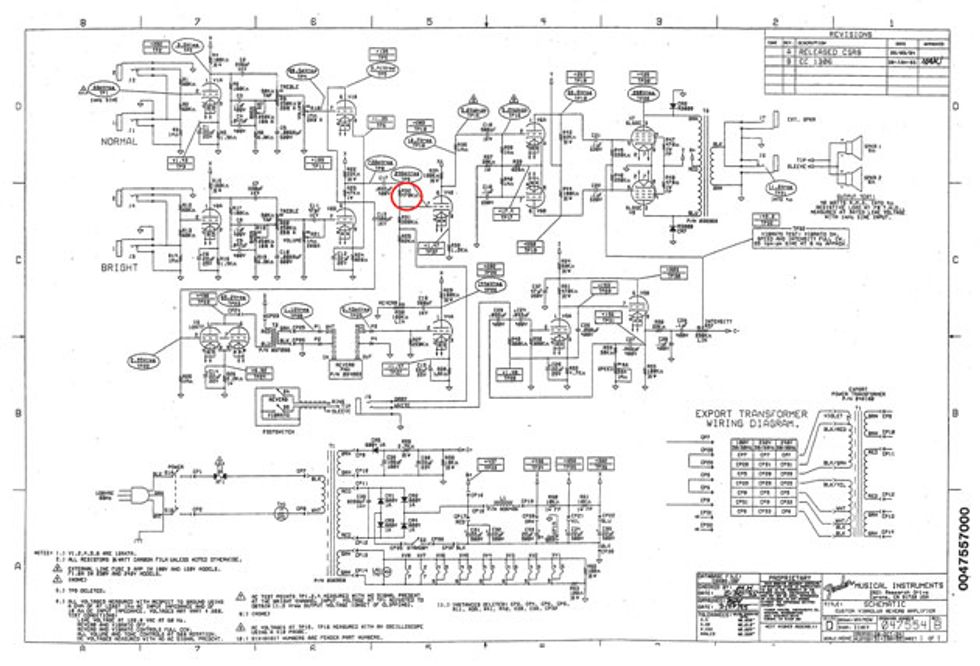
Fig. 3
Now let’s look at a couple of other mods for these amps. We’ll start by correcting the reverb recovery and mixer circuits. In Fig. 3, R32 is highlighted. Remove this 470k resistor and replace it with a 3.3M resistor with a 10 pF capacitor in parallel across the 3.3M. Next, on the base of V4, connect pins 3 and 8. This connection increases the gain of V4, making up for the reverb signal drop caused by the 3.3M. It also adds gain to the mixer circuit and gives the amp a beefier low end overall. And who knows? Connecting the cathodes of the reverb recovery circuit and the mixer tube, as found in the original version, may restore some of the reverb’s vintage quality.
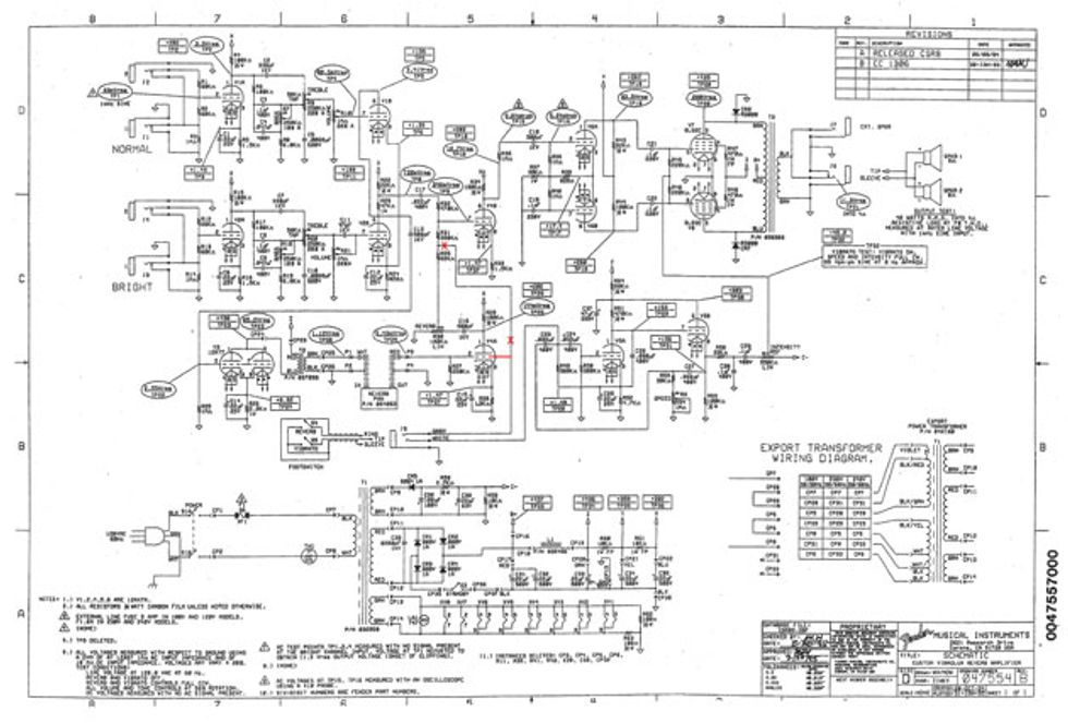
Fig. 4
Finally, let’s remove the reverb footswitch connection from the junction of R31 and R65 and connect it to its original location, pin 2 of V4 (Fig. 4). This also eliminates any tonal change when the reverb is switched off, something that might occur due to the other mods we’ve made.
Well, there you have it. Now you’ve got a Custom Custom!