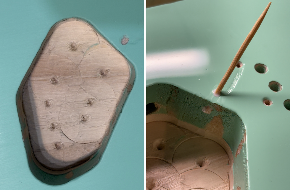

 Photo 1
In several recent installments of Mod Garage, we've explored projects that involve humbucking pickups with 4-conductor wiring. I've received many emails from readers who want to do some of these mods on guitars equipped with generic humbuckers, but when they try to determine which wire goes where in their pickups, they're stumped. They can't find a color-code chart online, and when they contact the guitar's manufacturer asking about the wiring, they often don't get an answer.
If your guitar sports brand-name pickups—like DiMarzio, Seymour Duncan, Fender, Gibson, or even one of the many boutique pickup makers—it's easy to suss out the 4-conductor wiring of the particular humbucker in your instrument. Chances are good you'll find a color-code chart on the company's website, and if not, these pickup makers typically have good customer support that can provide this information.
But when a guitar is outfitted with generic, unbranded pickups, it can be almost impossible to get the color-coding scheme. That's because these pickups aren't made at the guitar factory, but instead are supplied in large numbers by a specialized third-party manufacturer. Rather than following any standard, these suppliers use their own color coding and simply provide the guitar maker with instructions for installing the pickups in an instrument. As long as you don't want to change the factory wiring, all is good. But if you want to experiment with mods, you'll be out of luck because you lack the pickup's color-code scheme.
My rant. This is a huge nuisance. I can't understand why every pickup manufacturer feels the need to reinvent the wheel and use their own color-code scheme instead of a standardized chart. Good grief, people! As long as this nonsense continues, there will be no peace on Earth.
Pickup makers, if you read this: Why don't you all plan a nice relaxing weekend somewhere (perhaps on a beach with umbrella drinks) with the goal of resolving this simple issue? It shouldn't take more than 30 minutes to agree on a standard color chart for humbucker pickups. Your customers will be delighted and guitar techs worldwide will breathe a sigh of relief.
DIY cryptography. Fortunately, there is a way to solve the mystery of a generic humbucker's color-coded wiring.Sure, if you have a fully equipped workbench with a digital scope, a pickup analyzer, and some other high-tech toys, it's easy to crack the code—assuming you know how to operate these gadgets. But if you lack such high-end gear, I doubt you'll be inclined to spend big bucks on it just to determine a humbucker's internal wiring scheme.
So the question is, what's the easiest way to crack the code without breaking the bank? All you need is the cheapest digital multi-meter (DMM) you can find, a screwdriver, and a standard compass or a pickup magnet polarity tester (such as the very affordable Schatten device that's available from Stewart-MacDonald and other luthier-supply outfits). These items are a good investment for anyone wanting to mod guitar circuits.
Here's the step-by-step procedure for determining the color code of a generic 4-conductor humbucker.
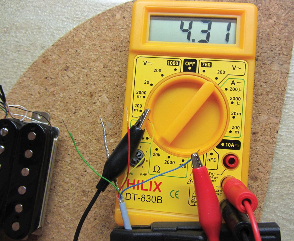 Photo 2
Step 1: Initial Prep
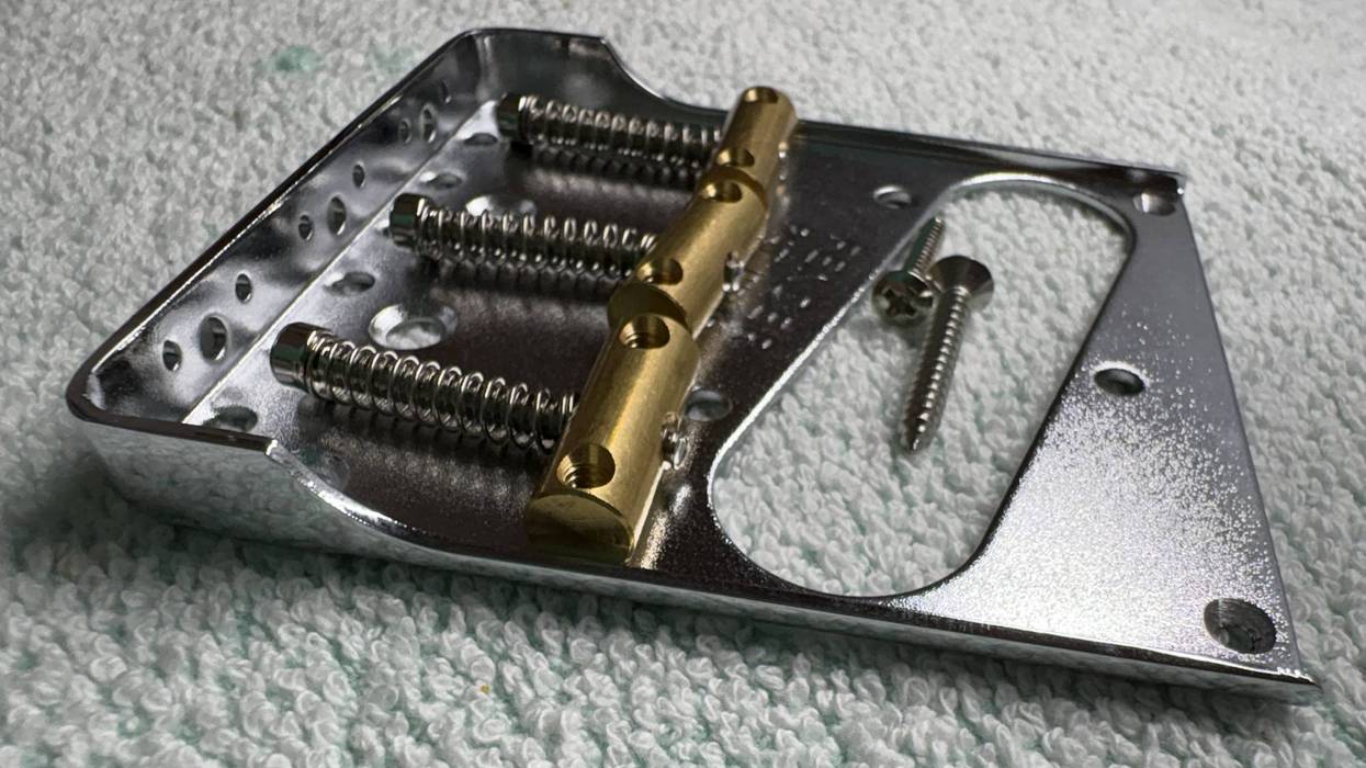
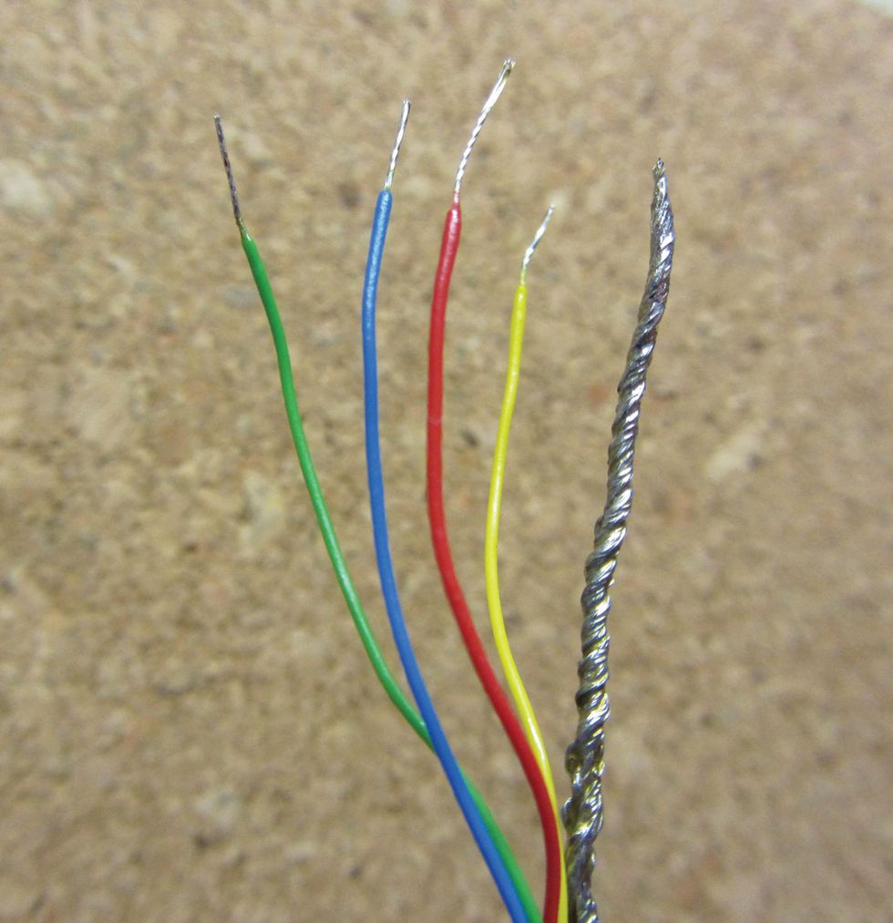
It's much easier to work with a 4-conductor pickup if you first prepare its wires. After stripping the outer jacket covering the humbucker's wires, you'll find four thin, insulated wires, often twisted with each other, plus a fifth bare wire that we can ignore for this process. Why? Because that bare wire always goes to ground. No exceptions.
Now separate the four insulated wires. To do this, you'll sometimes have to remove a thin plastic film that's around them—we don't need this now. Next, strip all four wires and twist their individual strands together. I like to pre-tin all four wires with a little solder, so the fine strands can't untwist again (Photo 1). This makes the following tasks much easier.
Step 2: Pairing the Wires
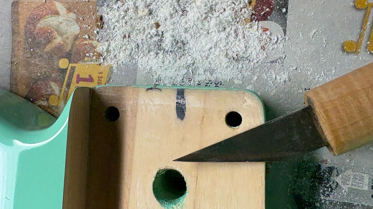
Switch on your DMM and set it to “resistance"—the 20k ohms setting is perfect for this. If you have a fancy DMM with an “auto range" function, you can simply set it to resistance, which is usually marked with a Greek omega symbol (Ω) and your device will do the rest. Alternatively, you can set your DMM to “continuity" for this step, if your DMM offers this function. Instead of a reading on your DMM, you'll receive an audio signal.
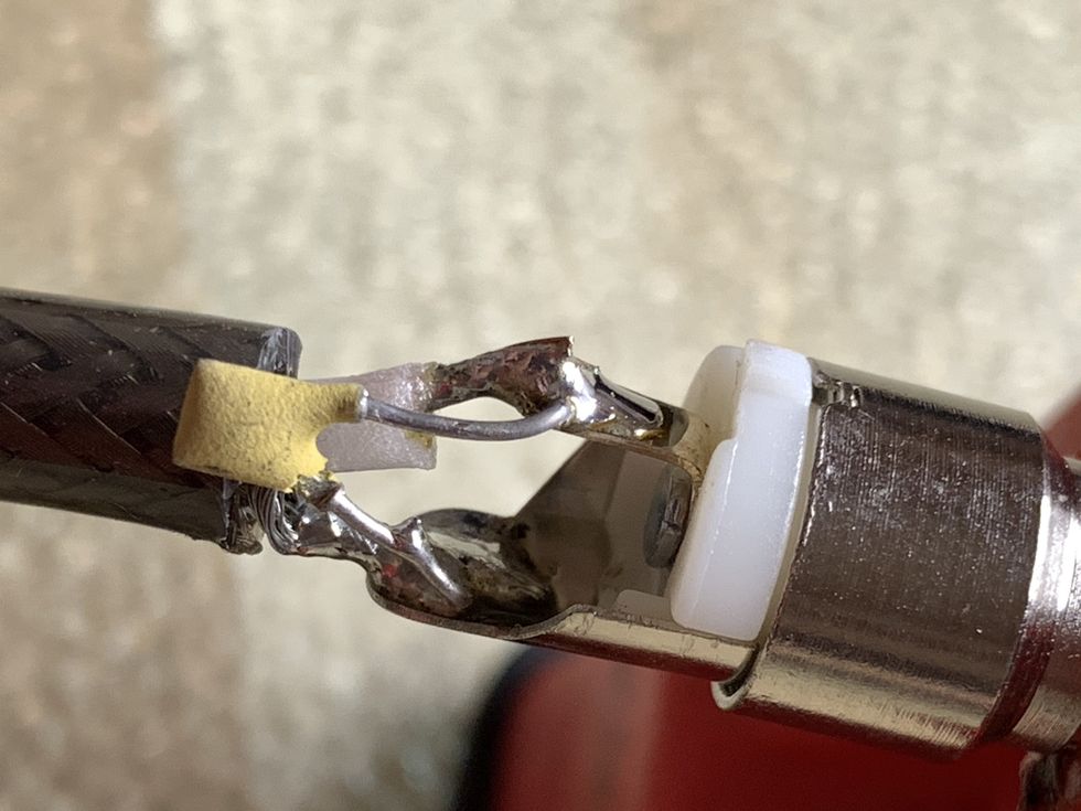
Next choose one of the four wires and touch it with the red probe of your DMM. Now touch every other remaining wire with the black probe. Only one of these three wires will give a reading on your DMM, showing the resistance of one coil, as in Photo 2. (If you set your DMM to continuity, you'll get a beep instead of a LCD reading.) The two wires that give a reading belong to the same coil. Mark them or make a drawing, whatever you prefer. The two wires that are left will also give a reading and belong to the other coil of your humbucker. Verify this by repeating the same procedure with these two wires.
Tip: Here's how to make the measuring a bit easier. Instead of using the DMM's two probes, you can connect standard 4 mm banana-plug cables to your DMM. Attach an alligator clip, preferably insulated, to one end of each cable, and plug the other ends into the DMM. The cables and alligator clips are inexpensive, and they're handy for all kinds of measurements.
Congrats—you've divided the four wires into two pairs, each belonging to one humbucker coil. This is an important step in our project. As far as our test humbucker, Photo 2 reveals the green and red wires belong to one coil, and the blue and yellow wires (shown) connect to the other coil.
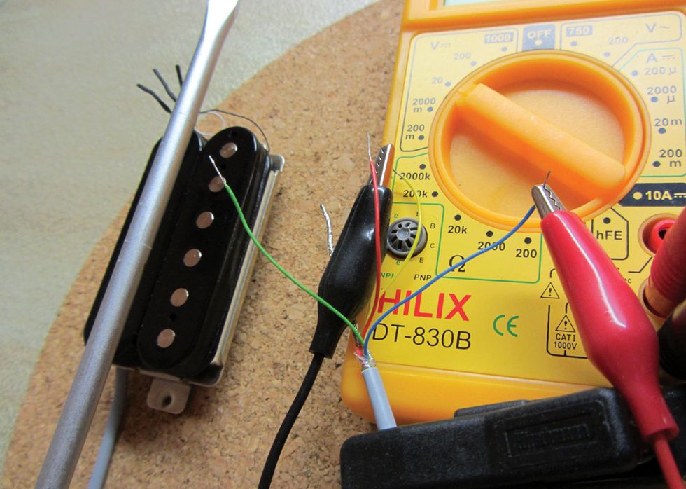 Photo 3
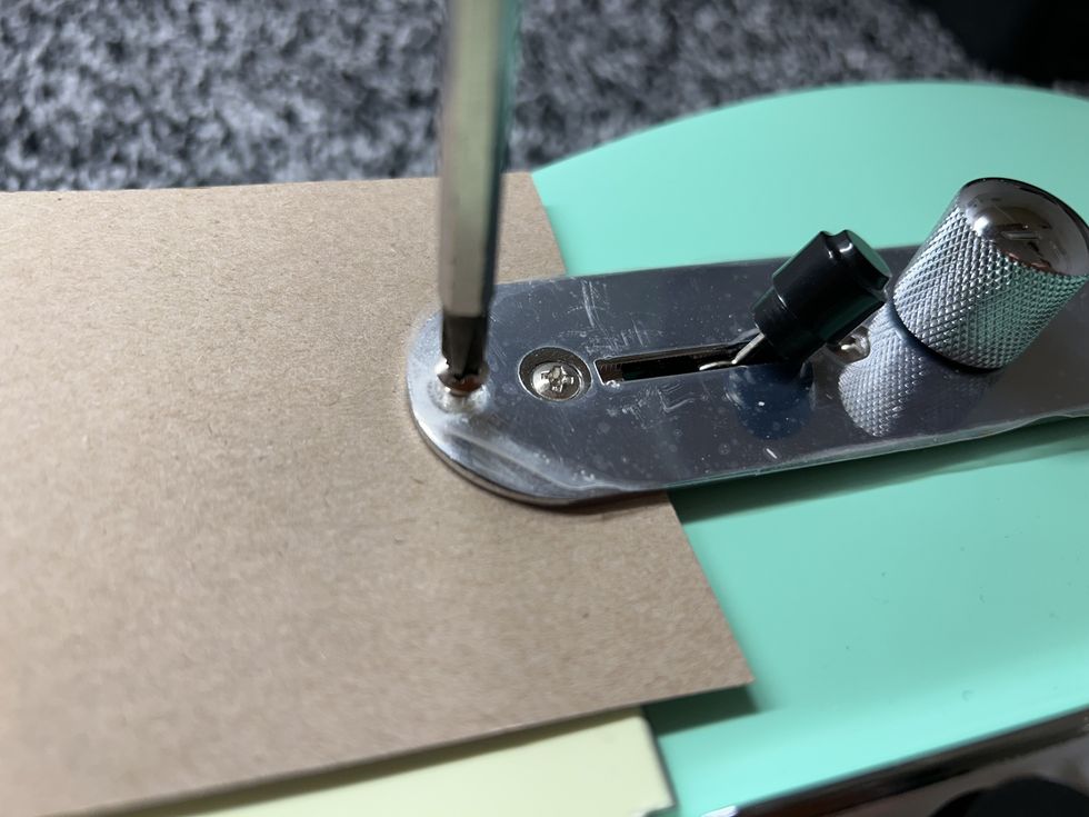
Step 3: Checking Phase
For the next step, you need to set your DMM to the 2 volts DC (direct current) setting, or if you have auto range, simply to DC. On certain DMMs, you also have to connect your probes or cables to the volts input for this test. Consult your DMM manual.
If you built the polarity testing unit from one of the recent Mod Garage columns, it will work for this step as well. To learn more, read “Build a Pickup Phase Tester, Part 1."
Note: If you have an analog meter with a needle, be careful with this step—you don't want to destroy the needle when it's moving backward. If possible, adjust your needle somewhere in the middle of the scale.
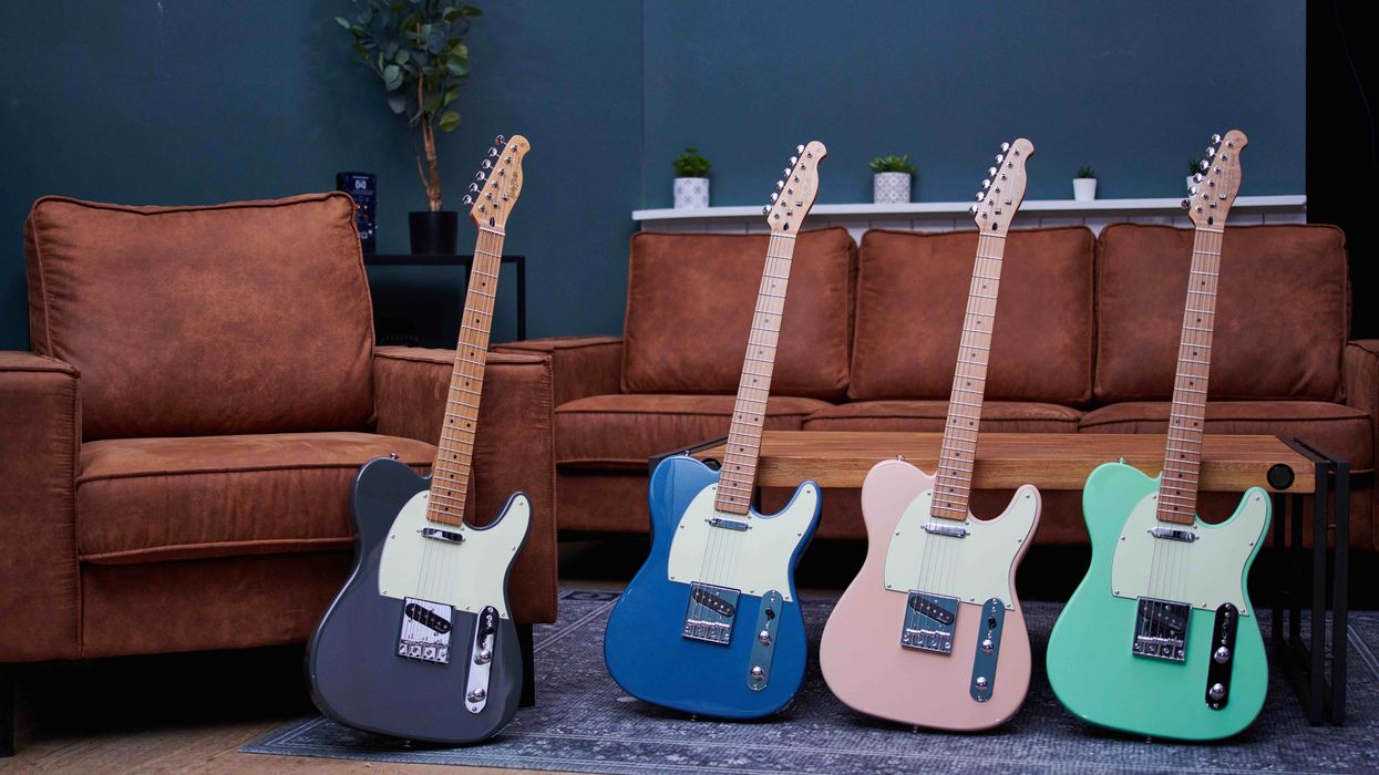
Connect your probes to two of the wires that belong to the same coil. In this case, I picked the green and red pair. I clipped the red probe to the green wire and the black probe to the red wire.
Now take a screwdriver, or any other piece of iron, and place it against one of the poles on one of the coils. Then remove the screwdriver and notice how the reading on your DMM goes positive and then negative—or vice versa—before returning to zero. It's important to resolutely tap the poles and remove the screwdriver quickly. Otherwise the reading won't be very clear.
Tip: To protect the humbucker, place a thin piece of cotton, like an old t-shirt, over the pickup so the screwdriver doesn't directly touch the pickup. The thin fabric won't influence the reading.
What we want is the reading that first registers positive when you tap the poles with the screwdriver, and then goes negative when you pull the screwdriver away from the pickup. This tells us that the two wires are in phase on this specific coil. If you're getting a negative reading first, reverse the two probes and try again.
I was lucky with the test pickup—I got a positive reading when I first touched the poles and a negative reading when removing the screwdriver. This tells us that the green wire (connected to the DMM's red probe) is the start of this coil, and the red wire (connected to the black probe) is the finish.
Next we'll determine which coil corresponds to the wire pair that's currently connected to the DMM. For this, perform the screwdriver test on each coil. You'll notice that one coil will yield a much stronger reading than the other. In our case, the top coil produced a reading of 0.15, while the bottom coil only registered 0.019, so it's clear that the green and red wires belong to the top coil.
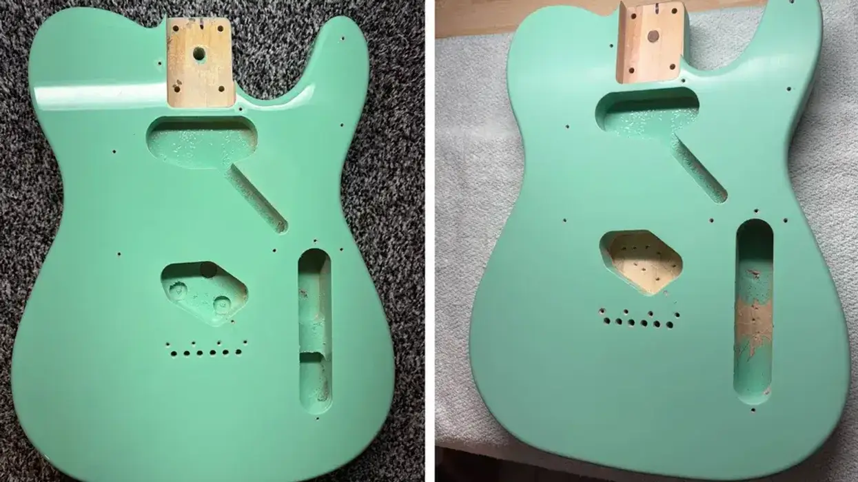
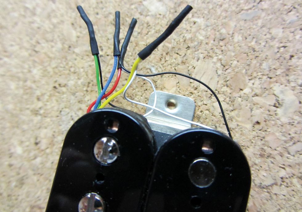 Photo 4
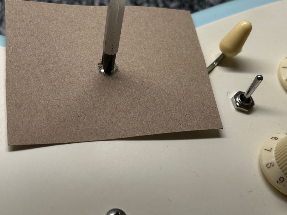
Step 4: Checking Magnetic Polarity
In our last step, you need either a pickup magnetic polarity tester or a simple small analog compass with a needle. (We dedicated a previous column to the topic of pickup polarity; click here if you want to brush up on the details.) A funny story about that column: Some weeks ago, a reader contacted me saying the compass trick I covered wasn't working with his pickups. After exchanging emails, it became apparent that for this test the reader was using his iPhone set to compass mode. I had to inform him that, regrettably, he'd need a real compass to complete the test. (Alas, few humbuckers are currently capable of sending GPS data. But who knows? It might be a good marketing gimmick.)
Anyway, at this point we want to determine the top coil's polarity. That's easy—simply touch the coil with the pickup magnetic polarity tester or your compass (not your smartphone) to see if it has a north or south polarity. In our test humbucker, the top coil's polarity was north.
Okay, we've been working with one pair of wires (the red and green pair on our test humbucker), but now it's time to turn our attention to the second pair of wires that belong to the other coil (blue and yellow, in this case). Clip your DMM to them and do the screwdriver tap test described above.
Because one of the coils in a humbucker has a reversed polarity, this time we're looking for a negative reading first. I got that initial negative reading with the red probe connected to the blue wire and the black probe connected to the yellow wire (Photo 3), which meant that in this coil, the blue wire is the start and yellow is the finish. The bottom coil also gave a stronger reading in the screwdriver test, confirming that it's connected to these two wires. Finally, repeat the polarity test on this coil (again using your tester or a compass). In our case, voilà! The bottom coil had south polarity.
Whoo—you're done! To master this operation, you'll need some humbuckers to analyze and a bit of practice, but it's worth the time and effort to learn this simple technique, because you'll gain a much better understanding of how a humbucker works. And, of course, you'll be able to reverse-engineer a generic humbucker's color-code scheme.
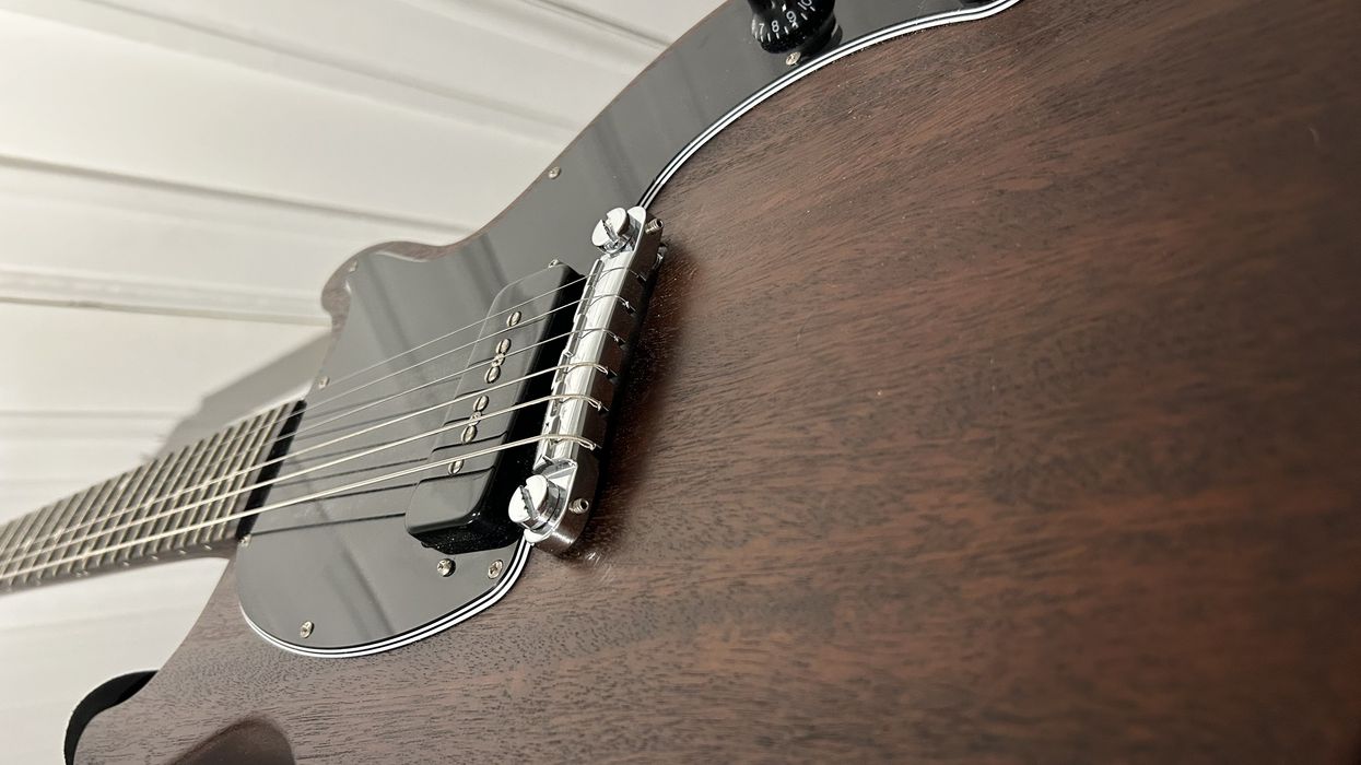
In closing, Photo 4 shows the internal connections inside our test humbucker, clearly revealing what goes where. Normally you can't see these connections, even with the metal cover removed, so a big shout-out to my friend Michael from the LeoSounds pickup company for custom-winding the humbucker I used to demonstrate the procedures in this column.
Next month, we'll dive into another guitar mod by analyzing what Fender did to add some silence to a split humbucker on their Select Carved Top Jazzmaster. Until then ... keep on modding!