
We'll break this down into two sections. Today, we'll talk about grounding in general and different ways to do it. In part two, we'll focus on grounding legs on the casing of a pot, like on the Stratocaster's master volume pot. And we'll come back to all this in a future column about how to shield pickguards and compartments the right way, which is also an important part of the grounding system.
Before we start, let's remind ourselves: We're talking about grounding in passive guitars, so we're talking about your standard Stratocaster, Telecaster, Les Paul, and the like. We're not talking about your amps, stompboxes, grandma's old steam radio, and other active devices.
In other words, it doesn't make a "better" grounding, but for showcase reasons, this is a cool option, anyway ... you hear with your eyes, too.
The good basic news is that it's not really hard to understand and you only need a simple digital multimeter, or DMM, set to continuity to analyze the grounding system in your guitar. I usually set it to audio or "beep mode," so you don't have to watch the display of your DMM. It's really simple: When it beeps, there is contact. If not, there is no connection.
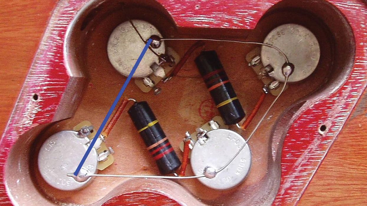
More good news: There's no "over-grounding." But there are things you can do wrong and then you're in trouble. My favorite on the "Grounding Pet Peeves" list is closing the ground ring on Les Pauls, ES-335s, and similar guitars. As you can see in Image 1, the ground ring is not closed, but many people like to add another ground wire, which I've marked blue, to "enhance" and complete the wiring because they feel that there's something missing. What happens if you do this? You created a perfect antenna to pick up radio and CB signals, so you can play along with your favorite radio station.
So, please don't do this. Sometimes less is more. Rant over … for now.
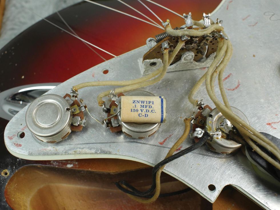
Image 2
Image courtesy of singlecoil.com
For today's guinea pig, I chose the Stratocaster, but will also elaborate on other guitars. Let's have a look at how to connect all casings together to ground them. The two basic rules of thumb are:
1. When your pickguard, control plate, or compartment is conductive, you don't need to add any ground wires to the individual components. They're already connected together because their metal parts are touching the conductive surface. This is the shield underneath a Stratocaster pickguard, the metal control plate on a Telecaster, or the metal "cage" you can find in some Les Paul models where the pots are installed through. But always try before you trust! Use your DMM set to continuity and do a test to see if the surface is really conductive. If it is, your DMM will show (or beep) continuity. This is especially important when you see black shielding paint anywhere in your guitar. It should be conductive, but in most cases, it's simply black paint to mimic shielding. On some models, like an ES-335 and similar, there is neither a shield nor any conductive paint underneath the top, so there is no way around using wires to ground all metal parts. If you're unsure, always run a wire from part to part to ground it. Even if the surface is conductive, it will do no harm to have double-grounding.
2. All this will only have an effect when you connect the system to the string grounding wire, by simply soldering it to the back of a pot, to the ground lug of your output jack, or to the copper foil underneath your pickguard, etc. Whatever you prefer. This wire usually comes from the tremolo claw in a Stratocaster, from underneath the bridge plate in a Telecaster, or from one of the studs on a Les Paul, ES-335, etc. If you are unsure which of the wires is the right one, the test is really simple: Use your DMM with one probe on the stripped wire you want to test and the other touching one of the metal strings. Continuity? Congratulations, this is the string grounding wire.
Image 2 shows the most minimalistic grounding version: Underneath your Stratocaster pickguard is a conductive shield (same for the Telecaster metal control plate). Install the pots and the switch and that's it. No additional wire connections are necessary, as the conductive shield will connect all parts. Use your DMM with one probe on the back of the pot and the other touching the shield, and then repeat this procedure with all three pots and the switch.
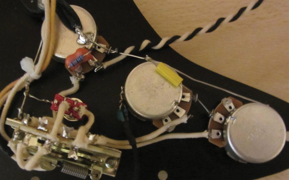
Image 3
Image courtesy of singlecoil.com
This is a Fender Stratocaster from 1959, and you can see there are no additional ground wires from pot to pot. The shield underneath the pickguard makes the connection and this is the way all early Fender guitars were grounded. Leo Fender was an educated accountant, well known for not wasting anything, and his defined goal was to build guitars in large quantities but in a short and cost-effective time. So why waste a piece of wire when you don't need to, and why waste time for such an operation when it's not necessary?
The second grounding version involves simply running a wire from one metal part to the next. This can be an insulated wire or a bare solid wire—sometimes tubing is used with bare solid wire to insulate it. The diameter of the wire is not important: A heavy-gauged wire won't make a better ground, in this case.
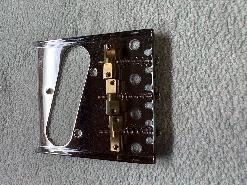
Image 3 shows the grounding version with simply a bare solid wire running from part to part. Image 4 shows the grounding version with tubing over the wire running from part to part. Please note that both pickguards in Image 3 and Image 4 don't have a conductive shield. Also note that there is a wire running from the volume pot to the 5-way pickup selector switch to ground it as well.
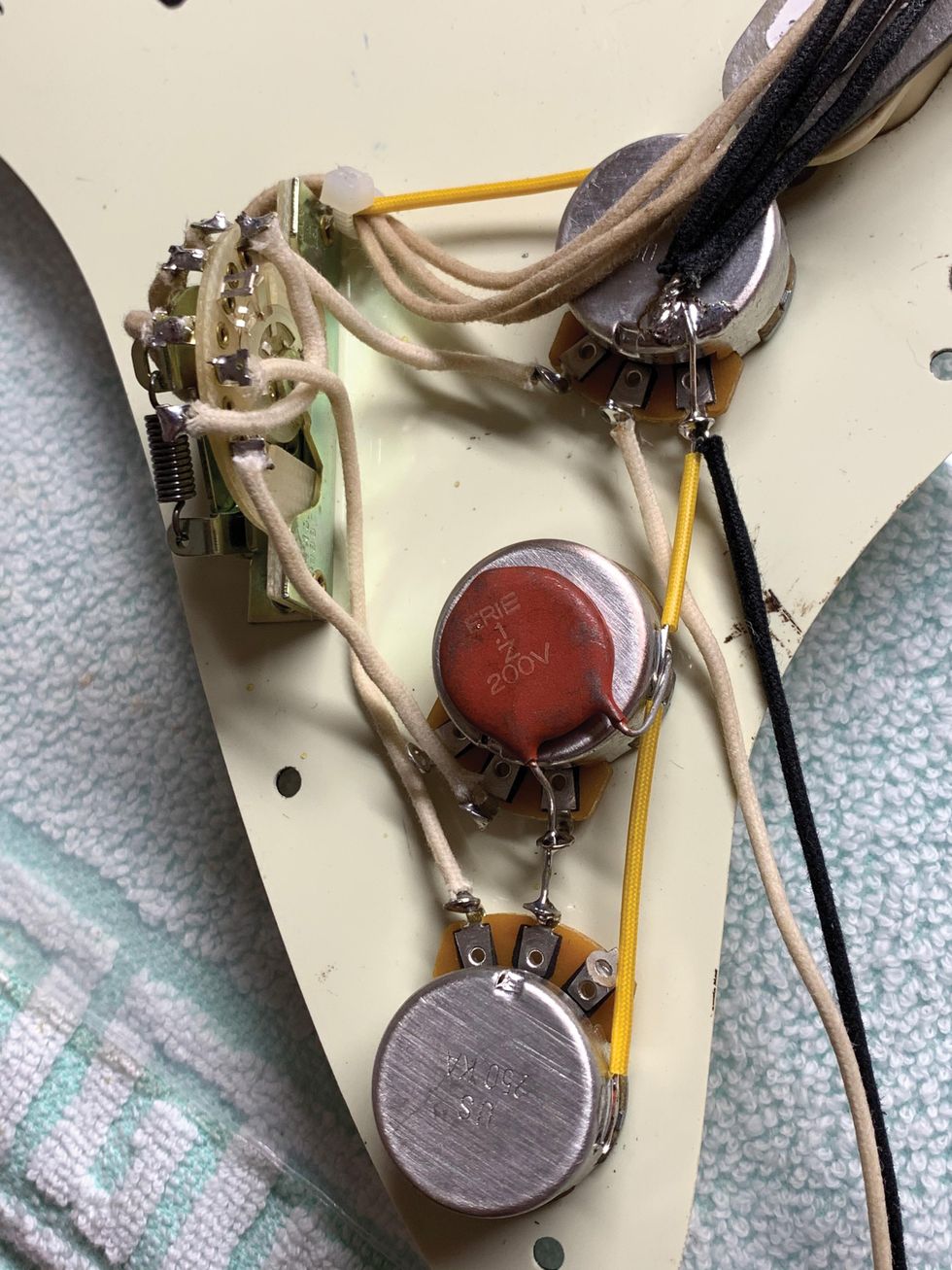
Image 4
Image courtesy of singlecoil.com
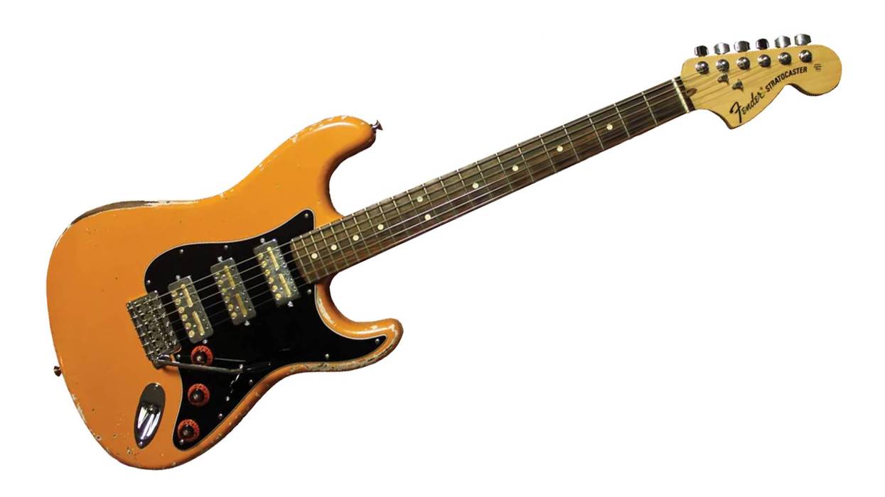
On some guitars, you can see that a ground strap is used to connect the parts, but this is the same principle and only a variation regarding materials. John "Dawk" Stillwell (may he rest in peace), the former guitar tech for Ritchie Blackmore, was well known for using this technique, and you can see what this looks like in Image 5.
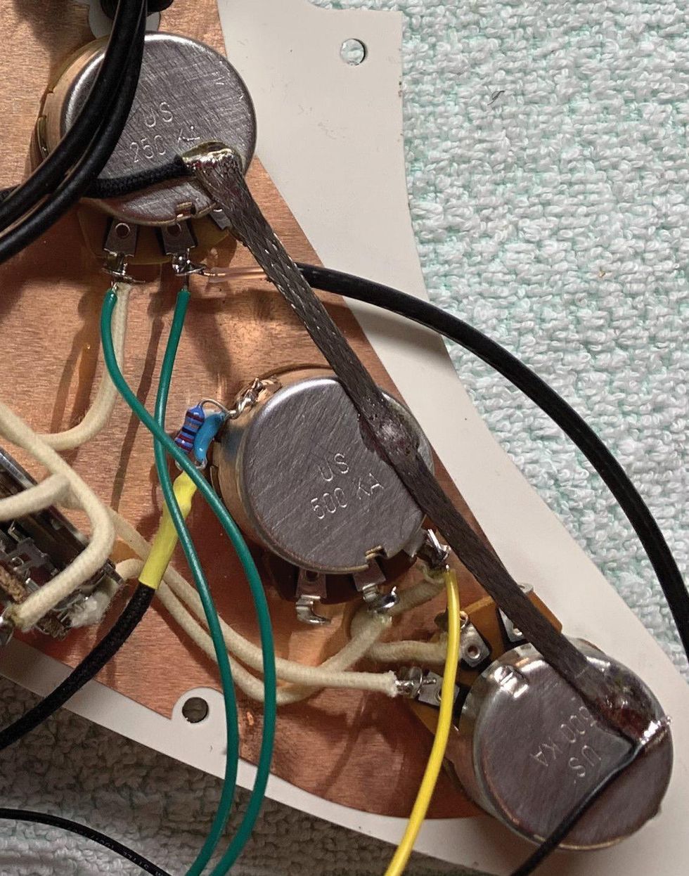
Image 5
Image courtesy of singlecoil.com
It looks pretty cool but has no advantage over using an insulated wire or bare wire. In other words, it doesn't make a "better" grounding, but for showcase reasons, this is a cool option, anyway ... you hear with your eyes, too. As you can see, this pickguard has a highly conductive copper shield, so any connection between the parts is obsolete anyway.
So, what version is the best, you might ask? For me, it's using a bare solid AWG 19 wire (also sometimes called "ground bus wire") that I only put sleeve on in certain guitars, such as a Les Paul. On all Fender guitars, and especially in any Stratocaster, I use it bare for some good reasons. With this technique, you can minimize the number of soldering spots and it offers some great advantages that you'll see in the second part of this series when we talk about grounding legs on pots.
Why is it important to minimize the number of soldering spots on the cases of the pots? It not only looks neat and tidy and saves time and material (Leo Fender would have chosen this technique for sure), but it also minimizes the risk of damage from overheating, which is the most important reason for me. The easiest way to damage a pot is to overheat it, especially when attaching a ground wire to the back casing. It usually takes 60 watts of power for this, and with a wrong soldering technique this can be a real disaster. I've discussed this topic before, but if you aren't familiar, read my column "How to Install and Maintain Your Guitar's Pots," from the May 2020 issue.
I'll share two advantages, shown on a Stratocaster, of why I prefer this technique. (I'll give more advantages in the sequel installment of this column).
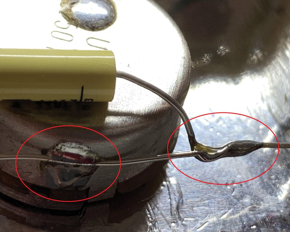
Image 6
Image courtesy of singlecoil.com
In Image 6, you can clearly see on the casing of the pot that there is only one soldering spot to connect the wire. With an insulated wire running from pot to pot, you would have two soldering spots or you have to heat it up for a second time. Next, look at the leg of the tone capacitor that needs to be connected to ground. Instead of making an extra soldering spot for it on the case or heating up an existing soldering spot for a second time, I simply solder it to the ground wire and that's it. The still unpopulated soldering spot on the back of the case is for the string grounding wire.
That's it, for now. Next month we'll continue our relic'ing project, focusing on the pickup and its cover, so stay tuned.
Until then ... keep on modding!