
Welcome back to Mod Garage. After receiving numerous requests to show more DIY tools for guitarists, today we’ll explore one of my favorites. For years I’ve used this one in the shop daily and I’m sure you’ll love it. It’s cheap and easy to build, but very effective for analyzing circuits of electric guitars and basses without opening the electronic compartment or lifting the pickguard. It’s a kind of adaptor or extension to measure a pickup’s DC resistance (DCR) from outside the guitar. After building one, we’ll discuss how to interpret the measurements.
The DCR of a pickup is by far the most common parameter you can read when reading pickup descriptions and often it’s used as an indicator of the output. The reason for this is that it’s easy to measure, but, sadly, it doesn’t tell us anything about a pickup’s output nor its tone. To quote pickup designer Bill Lawrence: “DC resistance tells you as much about a pickup’s tone and output as the shoe size tells you about a person’s intelligence.”
I’ve written about DCR as a pickup parameter in detail and you can read about it in “Mod Garage: Demystifying DCR.”
DCR is not a primary parameter in pickup design. It’s simply the result of the type and gauge of the pickup’s wire, the number of turns, and other parameters like the winding pattern, etc. But it isn’t completely useless, and we can use it as a good reference point for analyzing pickups both inside and outside a guitar or bass circuit. All you need for this is a digital multimeter (DMM). You don’t need an expensive calibrated precision DMM—any entry level DMM will work. You can get a simple digital DMM for $10, but if you want to invest in a better device, it can’t harm.
The easiest way to analyze a pickup is outside a circuit. Simply set your DMM to ohm and connect the two pickup leads to your DMM. If your DMM doesn’t have an auto-range function, set it to 20k ohm. Now you’ll get the DCR reading for your pickup. You can compare it to the factory specs of your pickup and it should be close. If your DMM shows “infinite” or “overload,” you know the pickup wire is broken. Let’s say your pickup should read 7k ohm, but yours reads around 2-3k ohm. Your pickup likely has a short circuit somewhere in the winding. Used this way, the DCR is always good to quickly check if a pickup is alive or not.
To quickly analyze a guitar or bass circuit with one or more pickups, you first need to build the DIY adaptor tool this column is about. There are two different versions, and you don’t need much for this:
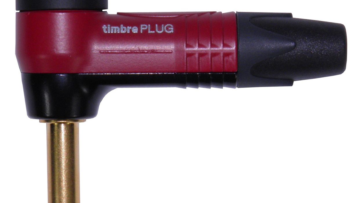
- Version #1: This is the quick and dirty version. You need a standard 6.3 mm straight mono plug (the same type on all your guitar cables), some wire of your choice (preferably in two different colors), and two insulated alligator clips.
- Version #2: A more elegant version that you can also use with a scope if you have one. You need the same parts as for version #1, but instead of two alligator clips, you need two 4 mm banana plugs, and the two wires need to be longer than what you’d use for Version #1.
So, heat up your soldering iron and let’s get to building version #1.
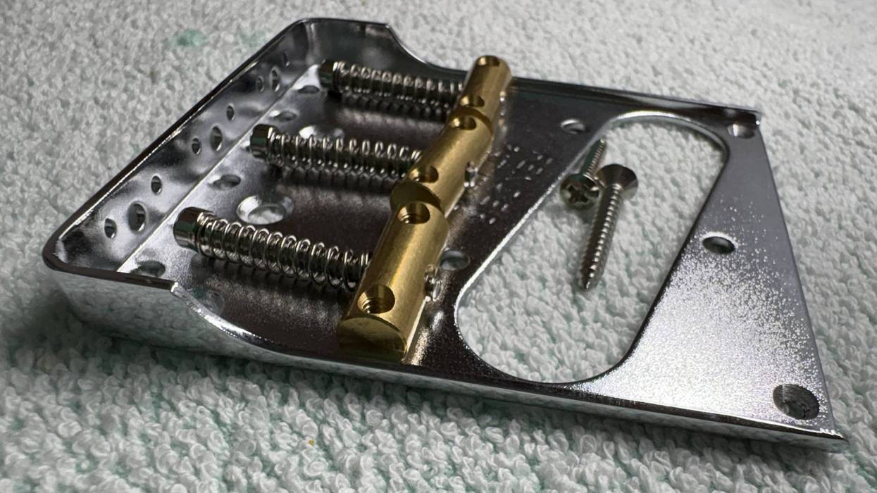
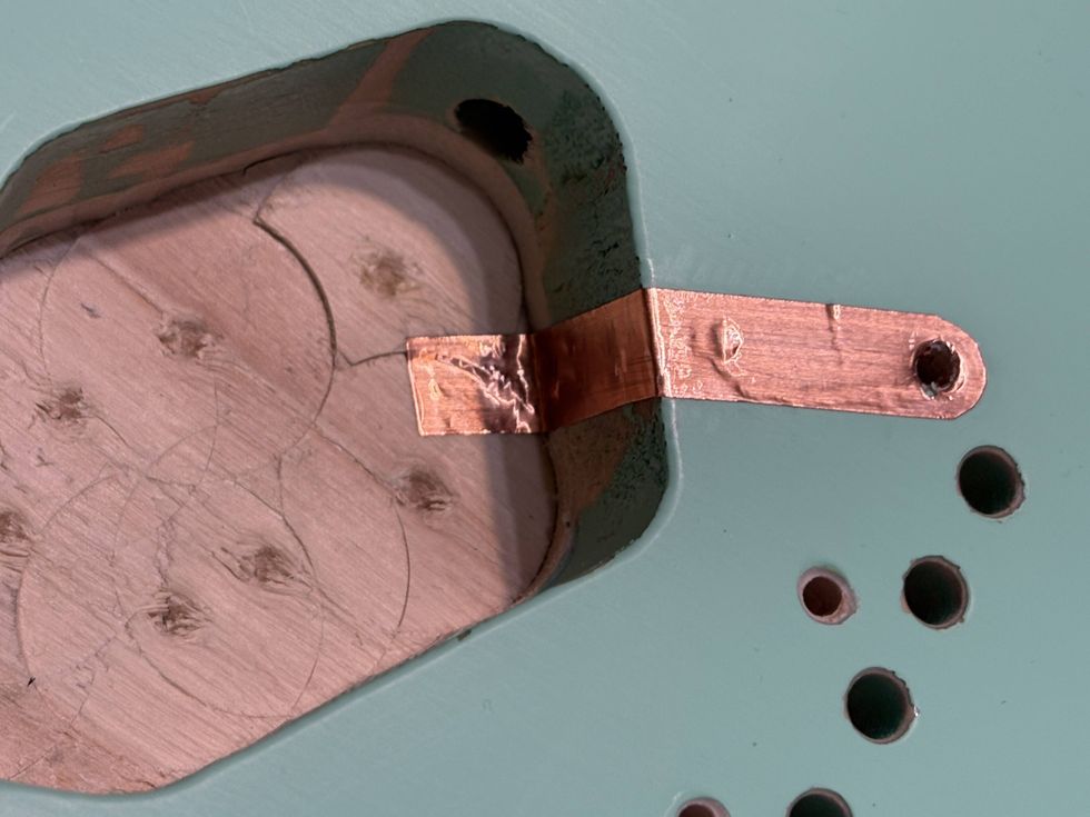
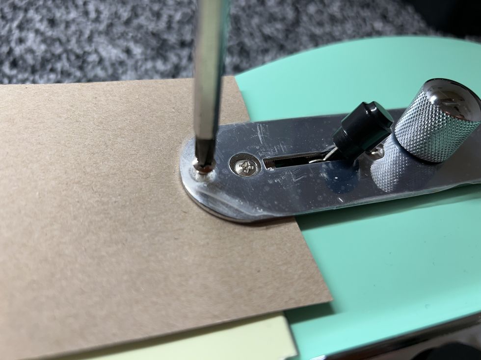
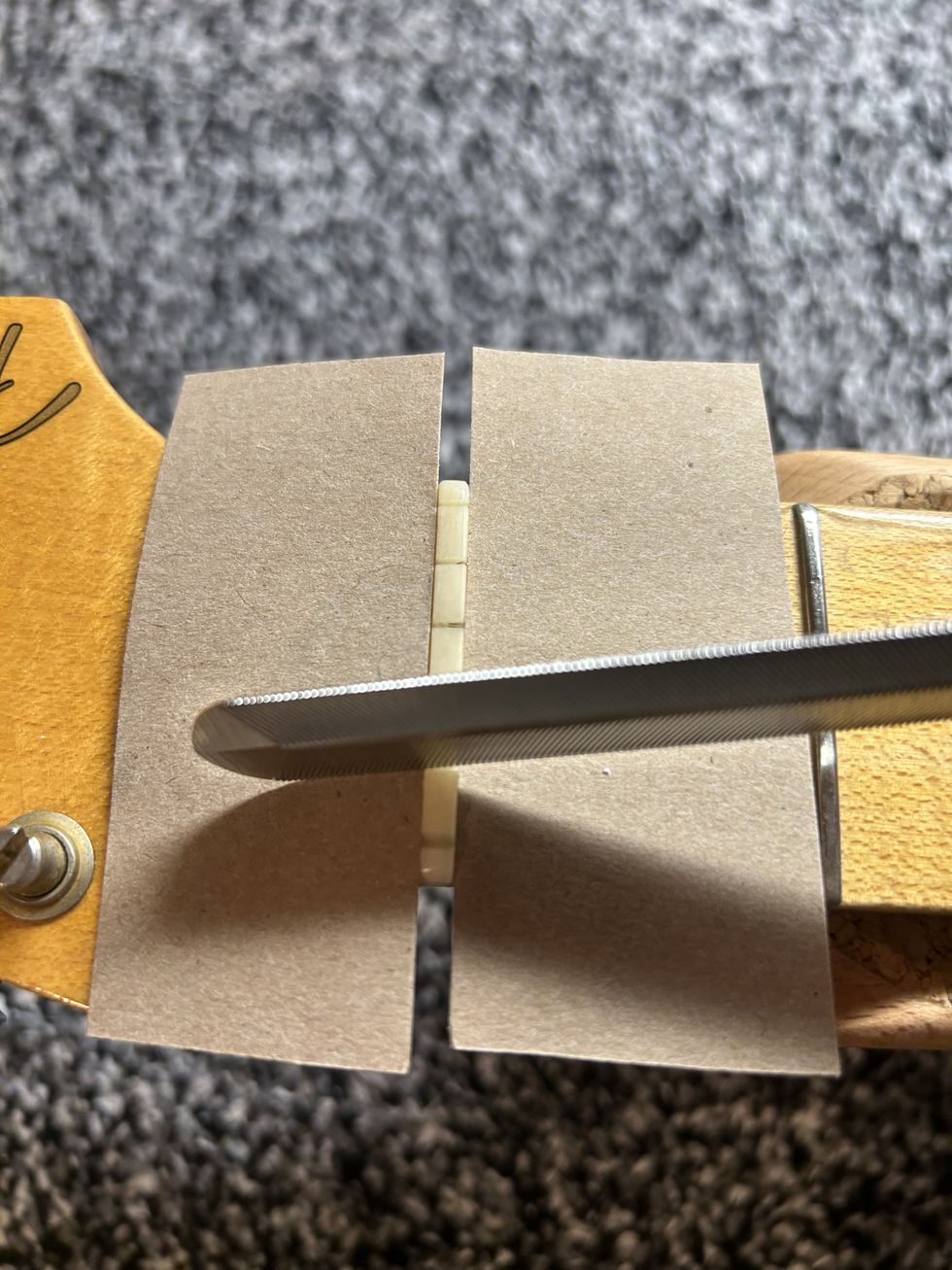
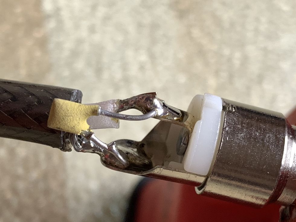
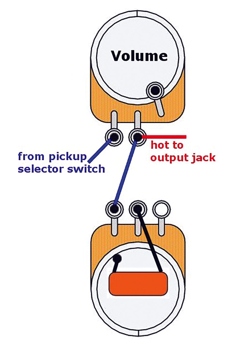
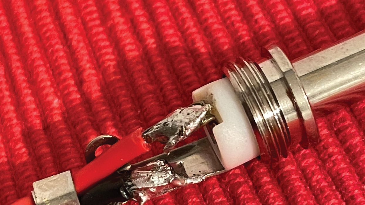
- Solder one piece of wire to the HOT terminal of the mono plug and another one to the GROUND terminal. I prefer a red wire for the HOT and a black wire for the GROUND terminal (Photo 1).
- Solder an insulated alligator-clip to each end of the two wires, preferably a black one to the black wire and a red one to the red wire. Ready!
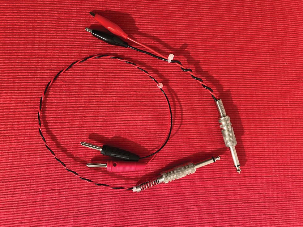
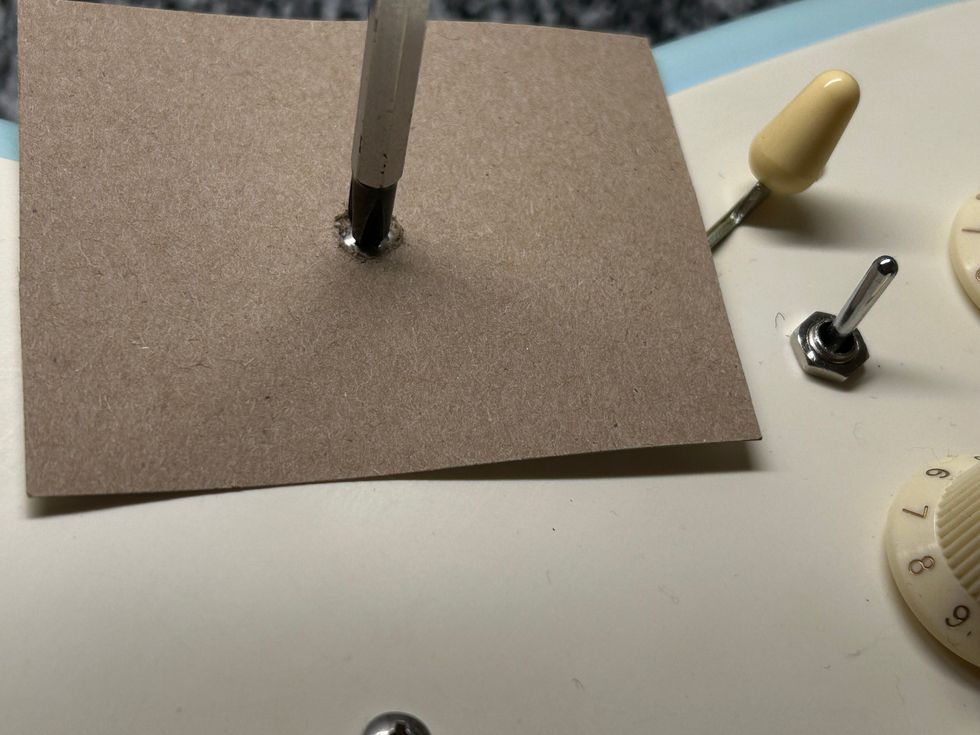
Version #2 is built the same way, but, instead of alligator clips, you solder a 4 mm banana plug to each end of the two wires, if possible, also in black and red. The two wires should be long enough that can place your DMM and/or scope at some distance from the guitar. In Photo 2, you can see version #1 on the top and version #2 on the bottom.
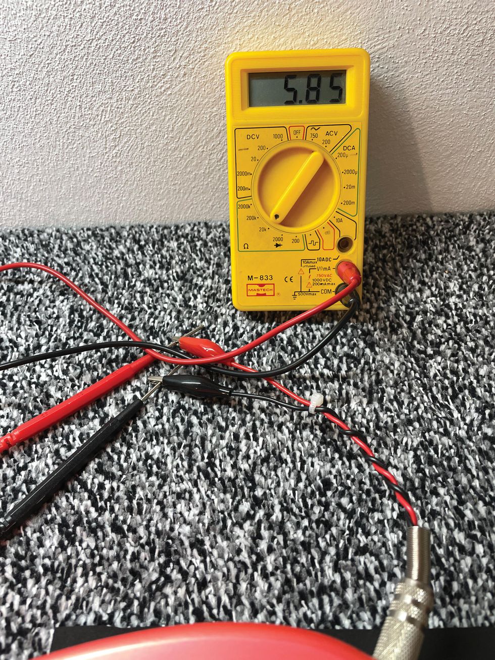
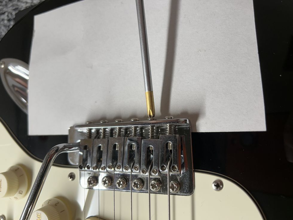
The difference between the two versions is that with version #1 you put the plug into the output jack of the guitar, connecting the two probes of your DMM to the alligator clips: the black probe of the DMM goes to ground (black wire) and the red probe goes to hot (red wire) as seen in Photo 3. With version #2, you need to remove the two probes from your DMM, plugging the two banana plugs directly into your DMM or your scope, also seen in Photo 3.
Both versions work equally well. Version #2 is just easier to operate when you also want to use the adaptor for a scope.
For a quick check, you can also directly touch the hot and ground terminals with the probes of your DMM, but you need both hands or a second person for this if you want to play around with the controls or the pickup-selector switch.
Now we can easily check four things with this tool, assuming everything is connected the way it should be and your DMM is set to ohm and auto-range or the 20k ohm scale if your DMM doesn’t have an auto-range mode:
- Do you receive a reading on your connected DMM? If not, check if the volume pot is fully opened. Do you receive a reading now? If so, close the volume pot completely and see if you still receive a reading. No? Perfect, you just proved that the volume pot is alive and well.
- With a fully opened volume pot and a reading on your DMM, slowly turn down the volume and watch the reading on the DMM. If you receive some crazy reading, chances are good there is a treble bleed network on your volume pot. If the reading slowly goes down to zero, you know that there is no treble bleed network on the volume pot, and you can check if it’s an audio or linear volume pot (plus the taper it has, if it’s an audio pot). Let’s say we have a 500k volume pot. When you close the volume pot halfway and receive a reading around 250k, you know it’s a linear pot. An audio pot, depending on its taper, will result in a much higher reading on the first 50 percent of the volume pot. If you read 500k until the volume pot is almost fully closed, this means the pot has a 90:10 audio taper—exactly the kind of volume pot you don’t want to have. If you read something around 300k in the middle of the volume pot, you know it’s a 60:40 audio taper.
- If the volume pot is fully opened and you don’t receive a reading on your DMM, chances are good that your output jack is broken, not connected, or connected incorrectly. Please make sure there is no activated kill-switch in the circuit that can also cause this “problem.”
- Turning the tone knob(s) will make no difference in the reading you receive. If you receive a slightly higher reading with a tone pot fully opened compared to when it’s closed, you know it’s a no-load tone pot.
There is a lot to discover from just the outside of any guitar or bass. So, now let’s see what we can measure from outside the instrument starting with a Telecaster with a 4-way switch. The readings in all examples are the readings I received with guitars I had in the shop, but they can be different in your instruments:
- Bridge pickup only: 5.85k ohm
- Neck pickup only: 6.76k ohm
- Both pickups together: 3.18k ohm
- Pickup selector switch in position #4: 12.30k ohm
The readings for both pickups are within the factory specs and are in a typical range for a vintage-flavored Telecaster pickup set. With a reading of 3.18k ohm for both pickups together, you know that both pickups are in parallel. With the reading of 12.30k ohm, you know that both pickups are in series with each other.
Here is the simplified math behind these readings:
- Series connection: DCR pickup #1 + DCR pickup #2
- In our example, it’s 5.85k + 6.76k = 12.61k ohm, which is very close to the reading of 12.30k we received. The missing 0.31k ohm are eaten up by the resistance of the pots and the tolerance of your DMM. For this test, I chose the cheapest DMM I could find in the shop. A calibrated high-quality DMM will have much less tolerance.
- Parallel connection: (DCR pickup #1 + DCR pickup #2) divided by four
- In our example, it’s 5.85k + 6.76k = 12.61k ohm divided by four = 3.15k ohm, which is very close to the reading of 3.18k ohm we received.
Now let’s repeat this with a standard Stratocaster:
- Bridge pickup only: 7.07k ohm
- Middle pickup only: 5.88k ohm
- Neck pickup only: 5.70k ohm
- Bridge + Middle pickups together: 3.26k ohm
- Neck + Middle pickups together: 2.94k ohm
All three pickups are within the factory specs of this Strat. We have a slightly hotter bridge and two vintage-flavored pickups. The two in-between positions are in parallel.
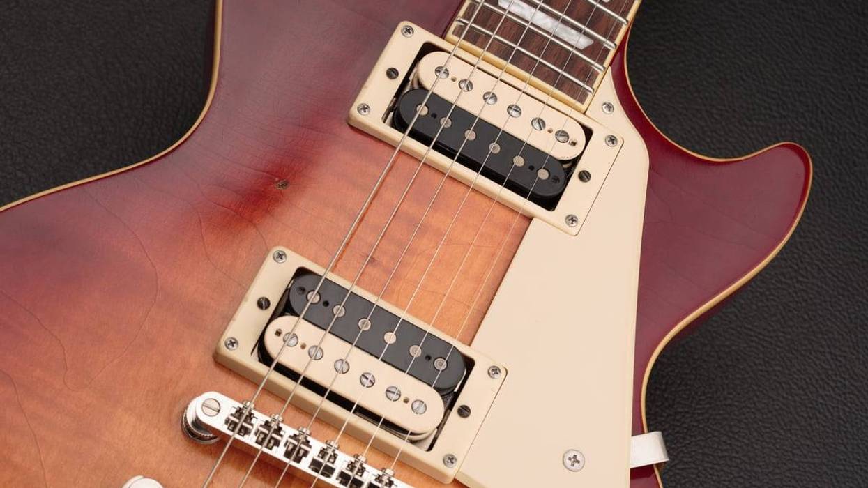
Lastly, let’s try a vintage PAF-loaded Les Paul:
- Bridge pickup only: 7.77k ohm
- Neck pickup only: 7.09k ohm
- Both pickups together: 3.74k ohm
Both PAFs have the typical vintage DCR and are in parallel in the middle position.
That’s it. Next month we’ll take a deeper look at changing wires on pickups, which is something I’ve been asked about a lot, so stay tuned!
Until then ... keep on modding!