
Recently a customer brought in his Fender Select Carved Top Jazzmaster to get set up for heavier strings. This model has a simple layout: two humbuckers designed to look like vintage Wide Range pickups, a Gibson-style 3-way pickup selector switch, and a classic Telecaster control layout consisting of master volume and master tone. The 3-way switch was configured like a Telecaster with the familiar switching matrix of bridge, bridge-plus-neck in parallel, and neck positions. It was a rock-solid guitar that played well.
The owner pointed out that the tone control had an additional switch to split the humbucker pickups. (This turned out to be Fender's S-1 switch.) He then requested an additional switch to flip from parallel to series in dual-pickup mode for some ultra-fat lead tones. While talking about this option, he mentioned he'd never played a humbucker guitar that offered such a cool single-coil tone when in split mode—sparkle and shimmer without hum and noise.
I became curious. My first thought was that Fender simply connected both humbucker coils in parallel, rather than shunting one coil to ground when in split mode. As you may know, when using this option, the humbucking feature is still engaged and you receive a pseudo-single-coil tone without hum and noise. Most humbuckers don't sound like real single-coils in this mode. Some say this configuration sounds more like a P-90, while others say it sounds like a cheap, thin humbucker. But I kept my customer's remarks in mind when I started working on his guitar several days later.
Because the electronic compartment of this Jazzmaster opens from the back, like on a Les Paul, I decided to do all the other work first, such as making a new nut and doing a complete setup for the heavier strings. When it came time to perform the electronic upgrade, I was surprised when I investigated the wiring.
After analyzing the wiring more closely, I realized what we had here: an adaptation of a wiring Bill Lawrence developed in the late '80s.
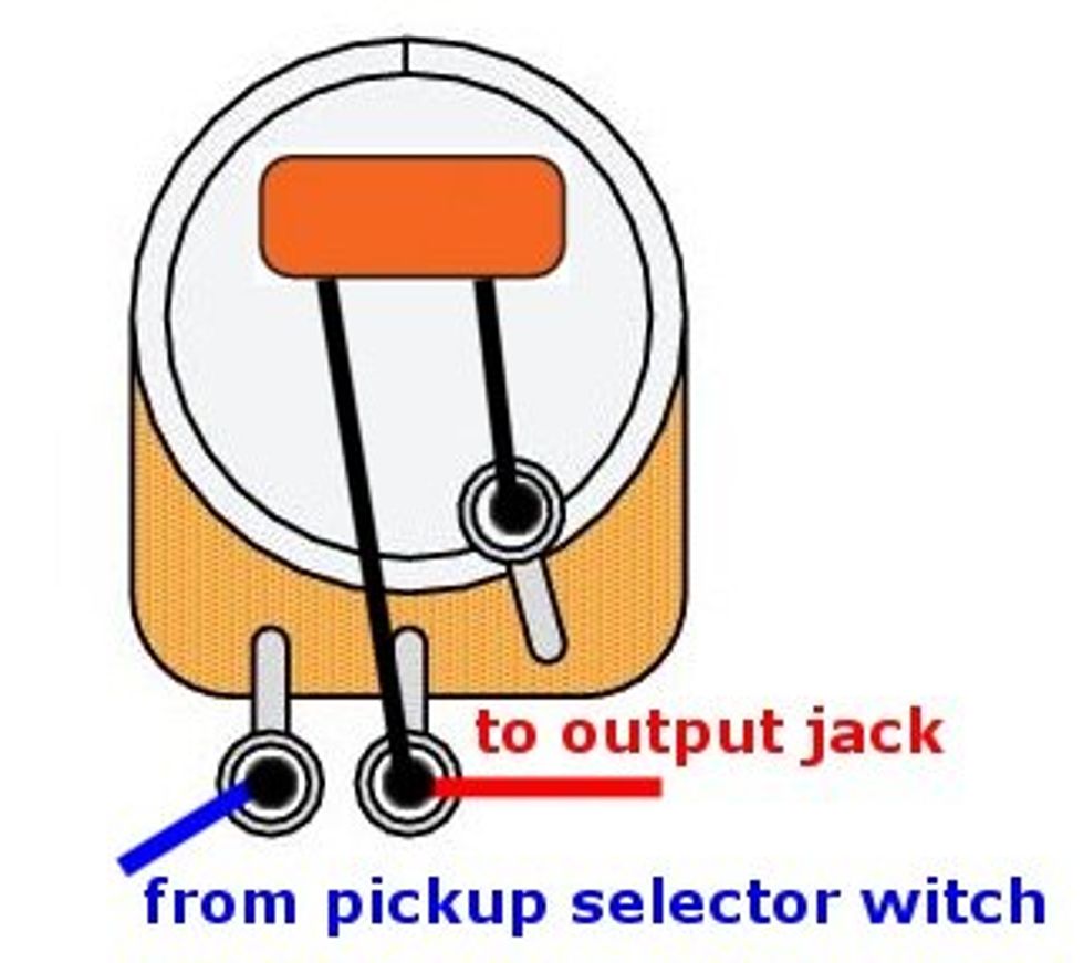
In addition to a resistor connected to the S-1 switch, I found a capacitor wired to it. Clearly, I had to dig deeper into this wiring, so I requested the schematic (Image 1) from Fender. Thanks to my friend Brett Leasure for immediately sending it over.
The 0.1 µF capacitor and standard 1.5k-ohm resistor rang a bell. After analyzing the wiring more closely, I realized what we had here: an adaptation of a wiring Bill Lawrence developed in the late '80s. Though this isn't new, it remains a very effective hum-reducing scheme. Let's see how it works and what it's doing.
When splitting a humbucker to emulate single-coil tone, one of the coils will typically be shunted to ground, leaving the other coil active with all the hum and noise that's associated with a single-coil pickup. That holds true for this specific wiring, but the two humbucker wires that are wrapped together are not directly connected to ground. Instead, they run through an additional RC network (0.1 µF C plus 1.5k R in series). In this network, the capacitor plays the most important role.
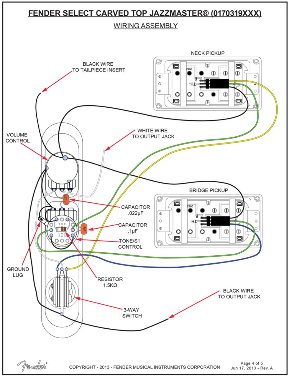
Image 1
The cap shifts the resonance frequency of the coil that's sent to ground, moving it down to near the typical 50/60 Hz hum territory. But that's not all—it also shorts out the frequencies we hear as tone. For the hum frequencies, the coil that's sent to ground is still active, but the tone frequencies—those located above the hum frequencies—no longer exist. In layman's terms: The pickup still operates like a humbucker (i.e., both coils are active) in the frequency realm of hum and noise. Yet for all tone frequencies, we're essentially in single-coil mode. The additional resistor mutes the superelevation resonance of the coil that's sent to ground. So this clever little trick works much like a "virtual dummy coil" when the humbucker is in split mode.
In a way, we can say we're abusing one of the coils by diminishing the mids and treble using a series RC network connected in parallel to the coil. The coil still "sees" the bass and hum and noise frequencies, and acts like a virtual dummy coil with the other fully active coil. This was Bill Lawrence's basic idea that Fender adapted to their wiring for this Jazzmaster.
As always with analog technology, there's no distinct separation at, say, 70 Hz. The virtual dummy coil covers the whole range of hum frequencies, but is also partly active above these frequencies, and it uncouples slowly. To create credible single-coil tone, the mids and treble must be uncoupled. The resistor is important because it allows an even transition when uncoupling the capacitor, so both components work together. This interdependence opens the door to experimentation.
Let's see what it takes to transfer this special Jazzmaster wiring to your humbucker-equipped guitar. We'll do this by transferring the S-1 switching matrix to a push/pull or push/push volume pot with a common DPDT switch that's connected to a humbucker for splitting.
 Basically, we can influence three parameters with the values of the two components:
- The voicing of the single-coil emulation (governed by the cap's value).
- Hum-cancelling effectiveness (governed by the cap's value).
- Voicing of the cap's uncoupling range (governed by the resistor's value).
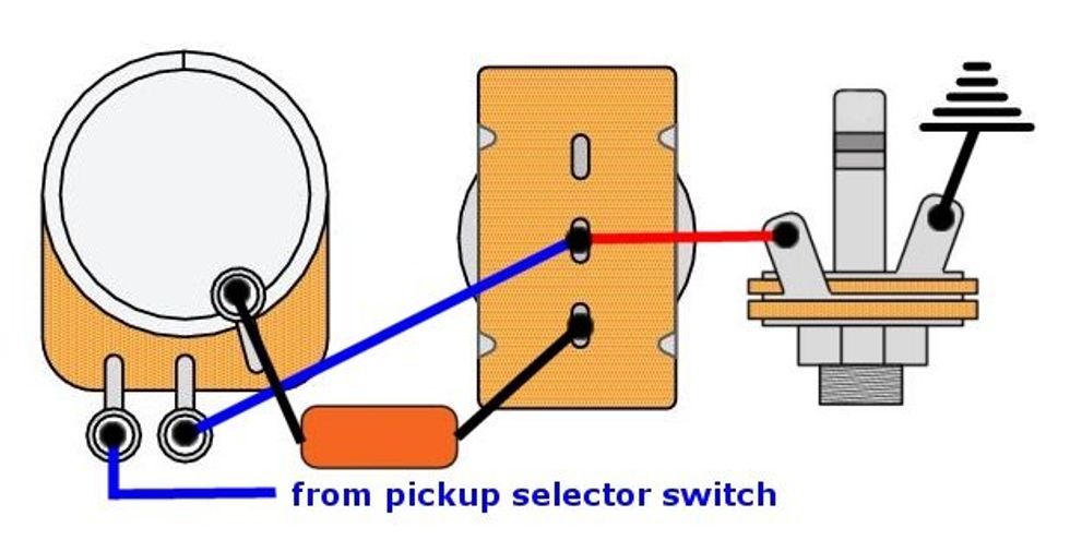
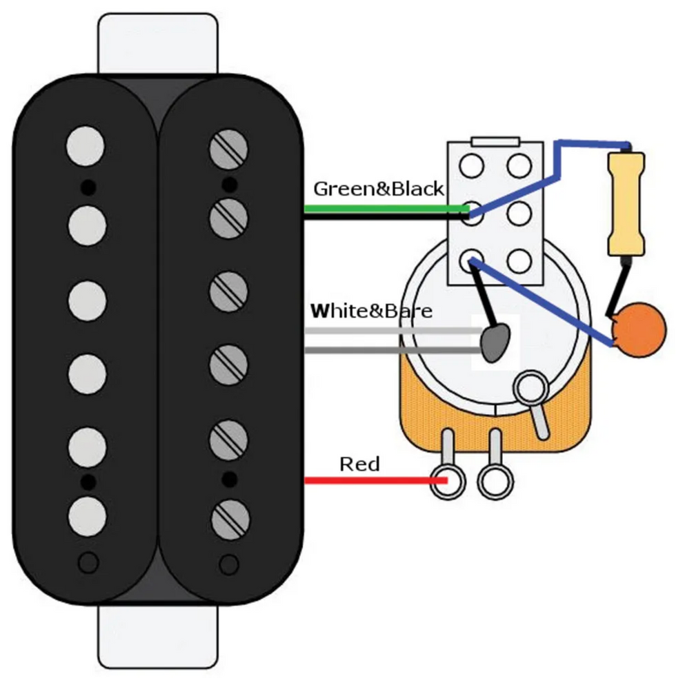
So as not to bore you with analog-system theory, I'll simplify some explanations that aren't critical to this mod. One common question is about the order used to connect the cap and the resistor in series. Actually, it doesn't matter, but from a theoretical point of view, electromagnetic compatibility (EMC) states the cap should be connected to ground as shown in Image 2.
I'm using the Seymour Duncan humbucker color code for this illustration. If you have a humbucker with a different color code, this should be easy to transfer. Of course, you can only split a humbucker when it has 4-conductor wiring that provides access to the start and finish of each of the two coils. If you have a humbucker with the standard 2-conductor wiring, you'll have to convert it to 4-conductor specs. Have this done by a qualified guitar tech or simply buy a new humbucker that comes stock with 4-conductor wiring. Let's see what happens when you tinker with the values of the two components.
Resistor.
Fender's 1.5k resistor creates a little hole (about -5 dB) in the mids, at around 2 kHz. Depending on the pickups and the amp, this can sound good. But when using Fender blackface amps, this isn't as desirable because of their inherent scooped midrange. Increasing the resistor value to 3.5k will eliminate the little hole in the mid frequencies. My personal favorite value is 3.9k ohm, which yields absolutely no mid hole. If you want more choices, you can wire a switch with two different resistors (for example, 1.5k and 3.9k) or use a 5k linear pot for a stepless control of this factor.
Capacitor.
The cap's capacitance lets us influence two factors, and we can deduce a relationship between them:- The smaller the capacitance, the better the hum-cancelling feature.
- The higher the capacitance, the better the single-coil emulation.
Here's a way to understand the cap's function in this wiring:
As the cap's value drops to zero, it's effectiveness is reduced. Zero capacitance is the same as using this wiring with no cap at all. With very high capacitance values, the coil will be shorted out more and more, until it is completely shorted, leaving only one coil still active.
A good range of cap values is from 0.01 µF up to 0.1 µF. You can use these—and everything in between—to balance the relationship between hum-cancelling and tone. The Fender value of 0.1 µF will result in maximum single-coil-like tone with a bit of hum cancelling—still much more than without the additional RC network. A 0.01 µF cap will result in a very high hum-cancelling ability (almost 40 dB), but with a tone that's quite fat and closer to a humbucker than a single-coil (think P-90 through a warm tube amp).
Explore these cap values, combined with resistor values from 1.5k up to 5k ohm, to dial in the midrange behavior. This will keep you busy for hours! For even more flexibility, you can implement a rotary switch with several cap values and a switch to turn the complete RC network on or off.
All this can be applied to our Fender wiring. Its stock values guarantee maximum single-coil emulation, but the downside—perhaps not for you—is less hum-cancelling and a tone that exhibits a midrange scoop. I think changing the values to a 3.9k resistor with a 0.047 µF cap will result in an authentic single-coil-like tone with no midrange cut, but with the benefit of greater resistance to hum and noise. In the end, it's about finding the right compromise, so experiment with the values of these two components to find a tone you love.
I'll be back with another project next month … until then, keep on modding!
[Updated 9/27/21]