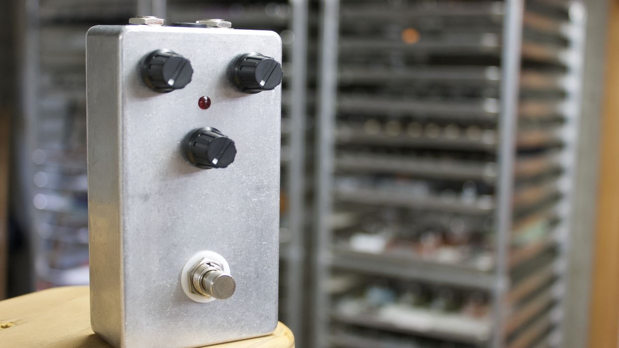
Pedals offer a lot of opportunities for DIY projects. One of the coolest and easiest is removing the LED clipping diodes in a modern overdrive pedal and replacing them with old-school-sounding germanium ones. The result will be a more raw, aggressive tone. For this project, I used the popular and affordable EarthQuaker Devices Plumes ($99 street). Whether your version is the original with through-hole-type components or the current model with surface-mount components, you’ll easily be able to perform this mod because both versions contain through-hole-type LEDs.

Tools Required
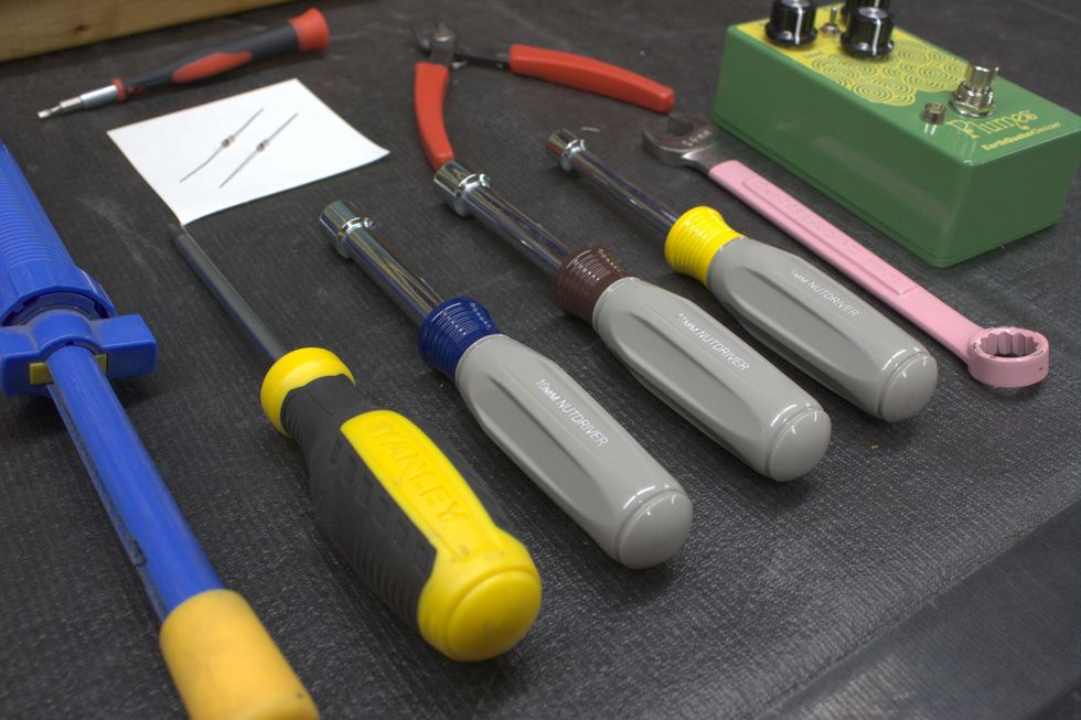
These tools and supplies are available online. StewMac, for example, sells soldering irons, a desoldering pump, and other tools for instrument work, while nut drivers and germanium diodes can be acquired via a number of sources, including Amazon.
• Soldering iron
• Solder
• Desoldering pump
• No. 2 Phillips-head screwdriver
• Small flathead screwdriver
• 8 mm (5/16") nut driver/wrench
• 10 mm (25/64") nut driver/wrench
• 11 mm (7/16") nut driver/wrench
• 14 mm(9/16") wrench
• Flush cutters
• Small needle-nose pliers
• Germanium diodes
Step 1: Remove back cover.
Using a No. 2 Phillips-head screwdriver, remove the four screws holding the back cover on.
Step 2: Remove external hardware.
The fastest way to swap diodes may be to do it from the component side, without even removing the circuit board from the enclosure. But for easier access and less difficulty, I’m going to remove the entire printed circuit board (PCB) from the enclosure. Since almost everything is mounted directly to the PCB, this should be easy.
Using a small flathead screwdriver, remove the knobs from the potentiometer shafts. Only loosen the knob set screws enough to slide the knobs off. No need to be searching the floor for tiny screws.
Next, using an 8 mm (5/16") nut driver or wrench, remove the nut from the toggle switch. Then, using a 10 mm (25/64”) nut driver or wrench, remove the three nuts and washers from the potentiometers.
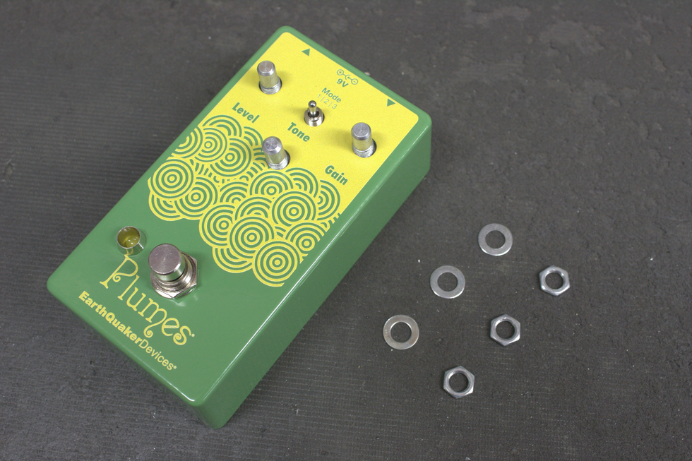
Photo 1
For the last piece of external hardware located on the face—the footswitch—we’ll actually want to go inside and disconnect its plug from the board.
On the bottom left side of the PCB, there will be a white rectangular connector. We need to unplug the female end from the male end. This is where small needle-nose pliers can help. A small screwdriver or even fingers may do the trick, too. Finesse is key. We don’t want to break the wires from the female connector.
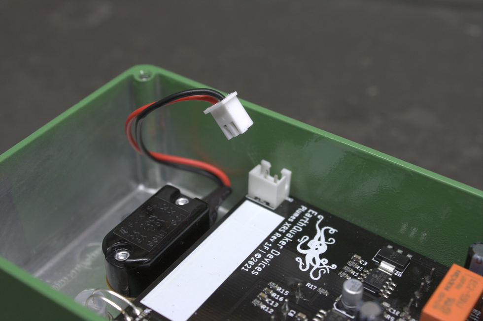
Photo 2
Once dislocated, we can go back to the face and remove the footswitch using a 14 mm (9/16") wrench.
Step 3: Remove external hardware on the back heel.
The last external hardware to remove is the audio jack bushings.
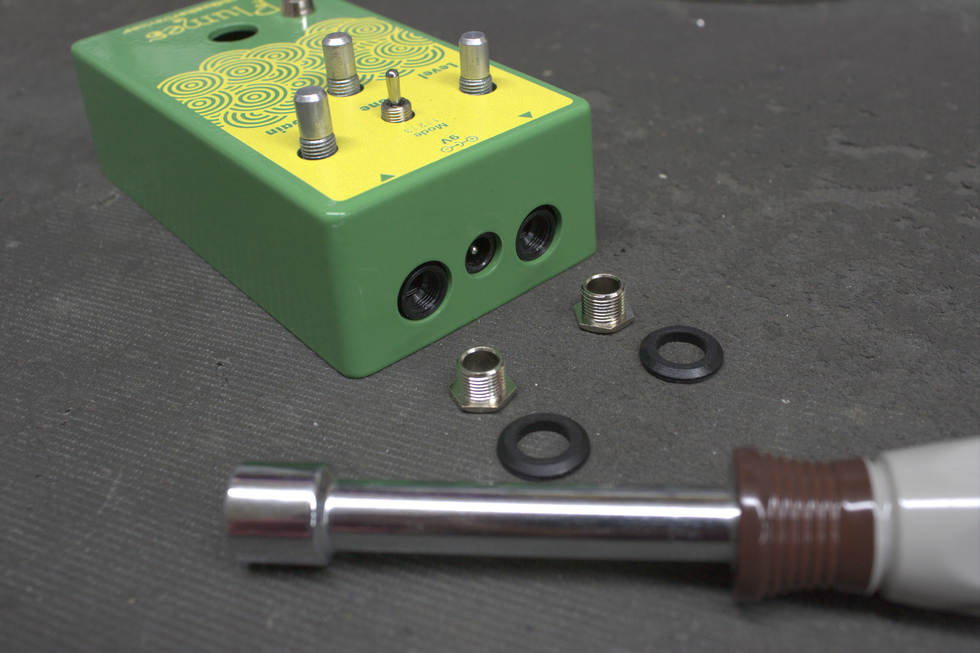
Photo 3
Removing these will allow the PCB to slide out of the enclosure. Using an 11mm (7/16") nut driver or wrench, remove the bushings and beveled washers from the audio jacks. Now, the circuit board is free to be removed from the enclosure.
Step 4: Remove the PCB from the enclosure.
The four controls and two audio jacks that interface with the enclosure may create some resistance when trying to remove the PCB. Typically, it’s from the collars of the audio jacks. Using a small screwdriver in one of the top corners and gently prying the PCB back usually does the trick.
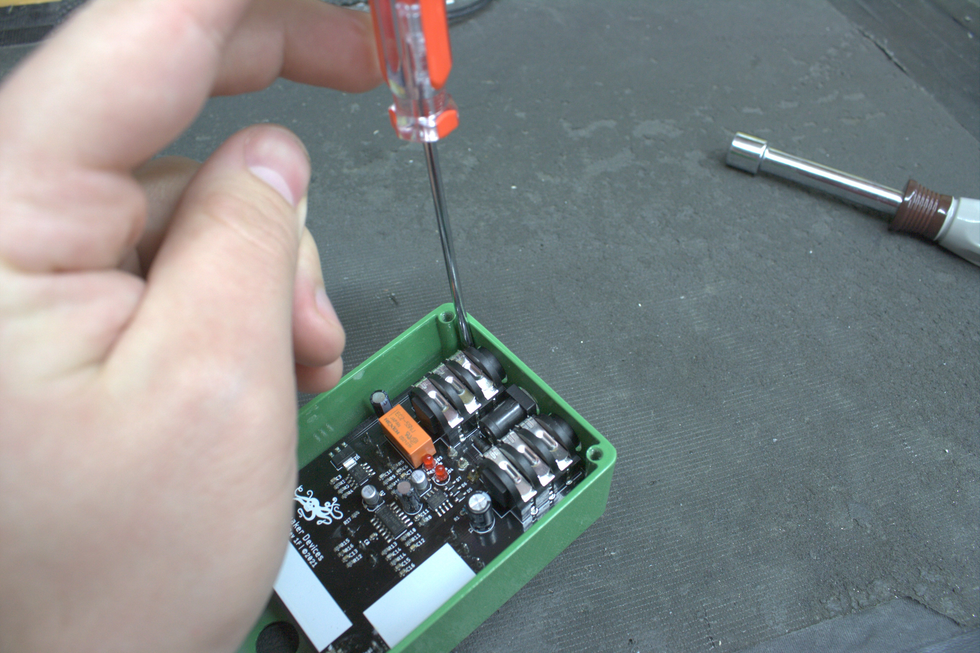
Photo 4
Step 5: Locating the clipping LEDs.
Now that the PCB is removed from the enclosure, we need to locate the clipping LEDs from the top side. They are the two small red silos at the center of the pedal.
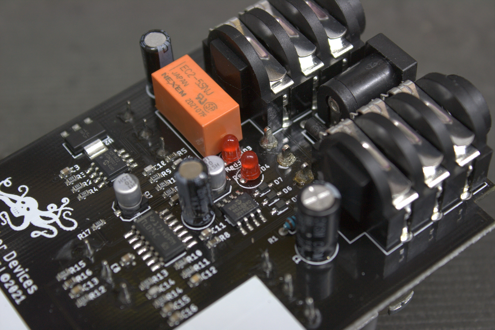
Photo 5
Then, we need to locate the pads (the exposed metal on the PCB) for them on the bottom side, and, once again, they are centrally located.
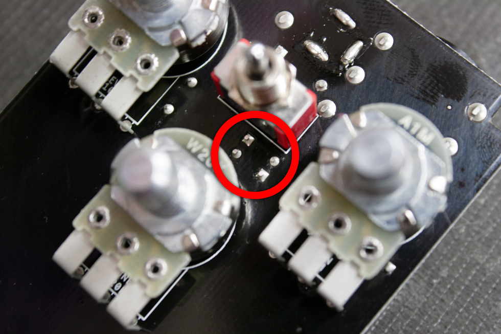
Photo 6
Step 6: Removing the clipping LEDs.
Now that we’ve located the LEDs, let’s go ahead and remove them. Quick note: The Plumes I worked on was a new unit consisting primarily of surface mount device (SMD) components. The LEDs are located between the pots and switch, so they can be difficult to access from the bottom side. The easiest way to remove the LEDs is to actually snip them from the top side, after noting how they are soldered in place.
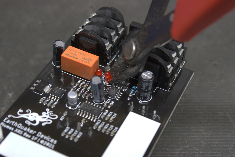
Photo 7
We’re not planning on using them, and they’re cheap enough to purchase again, so breaking them is no worry. We just need to be sure not to damage any of the nearby components. The best approach may be to break the shell/bulb of the LEDs. Doing this will expose the two leads.
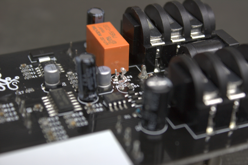
Photo 8
With these two leads exposed, we can easily remove each lead from the solder pads on the top side. Let’s apply heat to each pad and remove the leads with small needle-nose pliers. Jump to the alternate approach section in step seven if you experience solder removal difficulties. (Quick tips: Existing solder tends to flow better when a bit of fresh solder is applied to it. You’ll also want to heat the lead/pad and then grab the lead with the pliers. Grabbing the lead with the pliers first will take longer because the heat will transfer to the metal of the pliers. Don’t apply heat to a solder pad longer than needed. Doing this can compromise the pad.)
Once the leads are removed, we need to remove the remaining solder from the pads. This is where the desoldering pump (commonly referred to as a “solder sucker”) comes in. Apply a bit of fresh solder to the pads and remove it using the pump. YouTube is your friend here, for some quick desoldering pump lessons.
Step 7: Adding germanium diodes.
Check the polarity of the diode. For this mod, I chose 1n34a diodes, which are very common and available on Amazon. These diodes are polarized and have a positive and negative side. On the 1n34a, the negative lead is designated by the black band that wraps around the body of the diode (this is not the case for all germanium diodes). On PCBs, square pads denote positive. However, for the diode package that we’re adding, the square pad is negative.
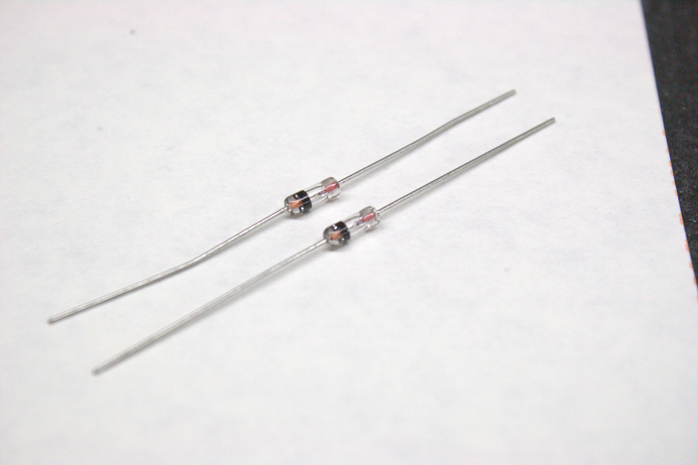
Photo 9
Using Photo 10 for reference, gently bend one of the diode legs so that it’s parallel with the body of the diode. Place the bent legs into their correct pads—the negative side of the diode will go into the square pad and the positive into the circlular pad. Solder the pads from the bottom side of the PCB and snip the excess leg length with a pair of flush cutters. The excess leg length can also be removed with needle-nose pliers by bending the legs back and forth several times.
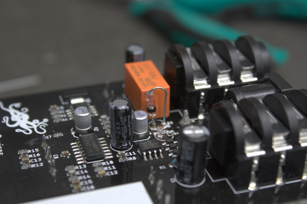
Photo 10
Alternate approach: If you’re experiencing trouble getting the remaining solder out of each pad, there’s a different approach to try. This approach may actually be helpful for this particular mod, because the pad spacing is small. If a pad connects to a ground plane (a layer of copper typically the size of the entire PCB that connects directly to the main ground pin on the DC jack) or several locations (other components in the schematic) it will require more heat because the applied heat wants to travel to all the connected areas. Typically, with clipping diodes, only one pad will experience this and give desoldering difficulties. In such a case, follow these steps:
1. Establish which pad has remaining solder. For this mod, the square pads are the positive pads, because they hosted LEDs. The diodes we’re adding want to have the negative side go into the square pad.
2. Cut the negative side of the germanium diode lead down to about 5 mm length. The negative side on the 1n34a is the lead closest to the black line indicator seen in Photo 9.
3. Heat the pad that has remaining solder in it and drop the short side lead into the solder.
4. Bend the other lead over like a horseshoe and mate it with the desoldered pad. (See Photo 10)
5. Solder the second side.
6. Repeat for the second diode, keeping in mind that the polarity of the diode needs to be opposite of the first diode that we soldered in as seen in Photo 11.
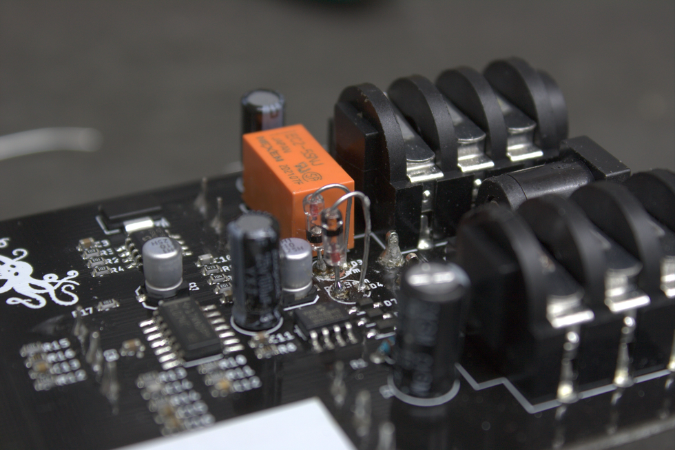
Photo 11
Step 8: Test.
Before putting everything back together, plugging the unit in as-is can be helpful. This way, if it isn’t working, we can go back and look at solder joints and any potential issues.
Photo 12
Step 9: Put everything back together.
Simply reverse the disassembly steps and enjoy!
A final note: If you love DIY projects or are interested in learning pedal design, my company, CopperSound, has a DIY section on its website, which also includes links to other DIY dealers. We offer integrated breadboards, component substitution boxes, adaptors for toggle switches, and even solder dispensers. For more information, please check out coppersoundpedals.com/DIY