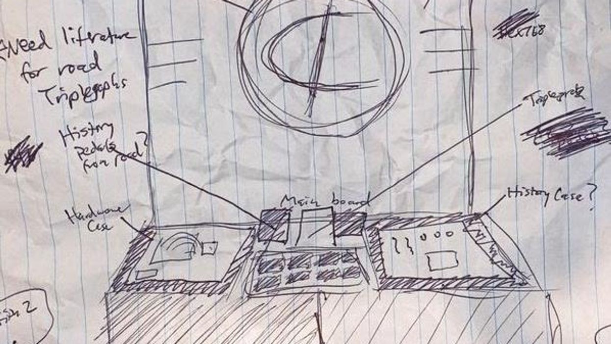

The DIY guitar-pedal world has been exploding over the past few years—so much so that it's likely at least a few of you have dipped a toe in already. I know I did. After using pedals for so many years and becoming pretty much obsessed with them, I felt a burning desire to learn what's going on inside these contraptions. But initially I was pretty intimidated. There is so much to learn! And even though we live in an age when all the information we need is practically at our fingertips, it's sometimes difficult to know how to word things in a search engine to get what we're looking for. Luckily, there's an immense DIY community out there, too—blogs, forums, and general-information reference sites. In my experience, just about everyone in the community is eager to help each other, so it didn't take long for me to feel welcome and encouraged.
Even so, two big things have become glaringly obvious to me during my years of pedal building. First, while there's a ton of information and lots of goodwill on the scene, there isn't really a single place that pulls together both the most important foundational concepts and a comprehensive list of the tools a novice needs to have not just a fun time, but a successful first building experience. No one likes spending a bunch of time and money on parts, tools, and assembly only to have a worthless hunk of junk that doesn't work at the end of it all.
Secondly, very few places mention one of the most important, helpful, and time- and wits-saving tools that a would-be pedal builder can have at their disposal. No matter how experienced you are, no matter what you're building, the simple fact is that if you don't have a circuit-tester box, you're probably losing a lot of time and getting way more frustrated than you need to during a pedal build.
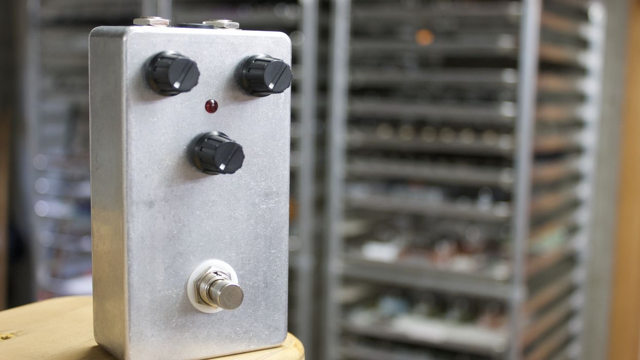
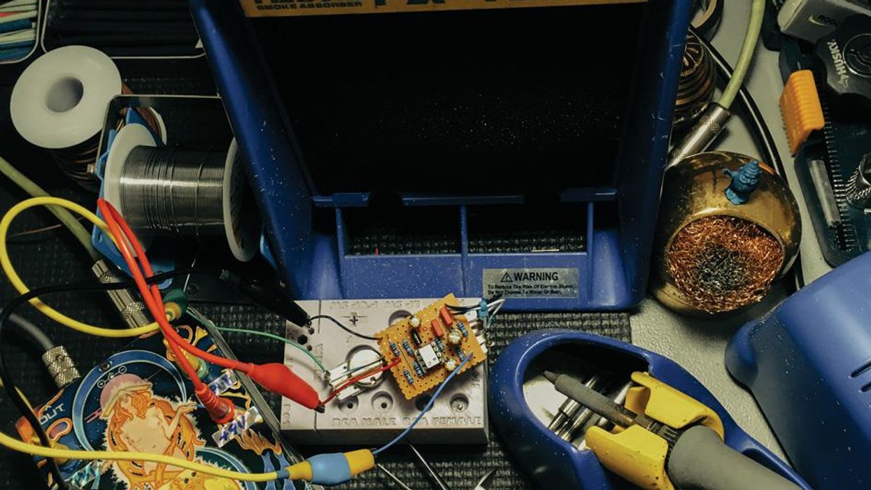
What exactly is a circuit-tester? It's a special, prewired "dummy" pedal you can use over and over again to test any circuit you're working on. In other words, it will function as the vicarious housing for any DIY pedal project you're working on, allowing you to hear it and know that it works before you install the project in a housing with its own jacks, etc. To that end, I put together this brief tutorial for a DIY tester box. Besides being very useful for any future pedal projects you might undertake, the tester-building process itself will be great practice for upcoming pedal builds, too. Once you've mastered this, you'll be ready to move onto building your first pedal, whether it's a kit or a copy of a popular circuit.
Let's start with essential tools, since there are so many options on the market that might seem fine but actually aren't well suited to pedal-building tasks.
Essential Pedal-Building Tools
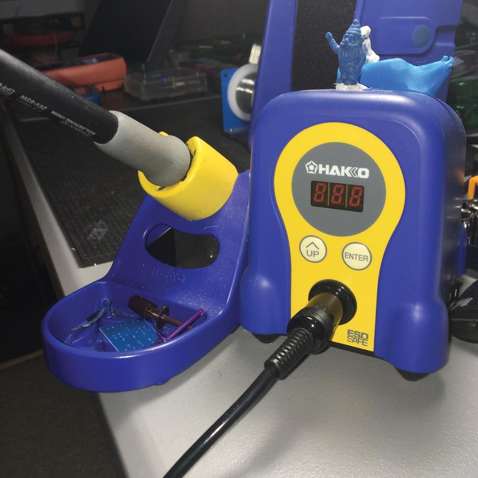
Soldering iron. You don't need the fanciest one around, but a cheapie can definitely make your projects a lot less fun. An iron of 40 or more watts will get the job done. And while you don't have to get one with a digital readout, it's a heck of a lot easier to use. Otherwise, you'd need to rig up a way to test your iron's temperature to ensure it stays at an appropriate, steady temperature for creating good solder joints. I solder at anywhere from 600 to 750 degrees, and I like the set-it-and-forget-it aspect of digital soldering irons. If the temperature drifts, the readout will reflect that fluctuation and readjust within seconds. I've tried about six different soldering irons, including an expensive Weller digital model. I keep going back to the Hakko FX-888D, but if you're not quite ready to plunk down a hundo on your iron, the Weller WLC100 40-Watt Soldering Station will work just fine, too.
Soldering tips. Soldering stations typically come with one soldering tip, usually a large one that's not very useful for pedal building. There are many sizes to choose from, but I tend to use two sizes mostly: a .8mm conical tip and, much less often, a .8mm chisel tip. In my experience, it is better to purchase original-equipment-manufacturer (OEM) brand soldering tips, as after-market tips often don't last long.
Solder. The type of solder typically used for this type of work has an activated rosin flux core and is composed of approximately 60 percent tin and 40 percent lead, although lead-free options are available. I have tried many kinds—lead-free, silver-bearing, no-clean, you name it. I've found lead-free solder incredibly difficult to work with, though perhaps I will find one that works for me in the future. Some folks like a bit thicker diameter of solder than the Kester .02"-diameter solder that I use. I find anything from .02" to .03" in diameter acceptable for pedal building. (Note: Even if you've been soldering for a while, I also recommend finding out more about it from a source such as ElectronicsAndYou.com. There's also a wonderful tutorial video by trusted electronics outfit Pace, Inc.)
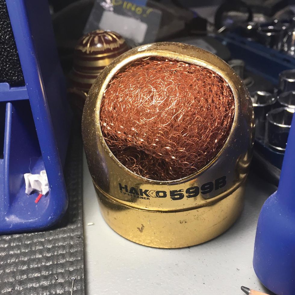
Something to clean your iron. This is something you should be doing quite frequently! A moistened sponge works, while something like the handy Hakko 599B Tip Cleaner helps prevent solder blobs from flying in your face or hair.
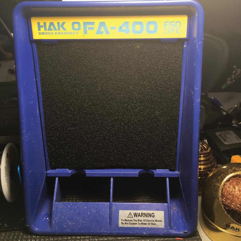
Smoke absorber. Solder fumes are highly toxic, so a de-fuming fan/smoke absorber is essential—even if you're working in a well-ventilated room. I use a Hakko FA-400, but I still keep all shop windows open and use a ceiling fan to keep the air circulating out. Placing a soldering station right next to an open window with the de-fumer blowing the fume-y air out is the easiest way I have found to keep solder smoke from lingering.
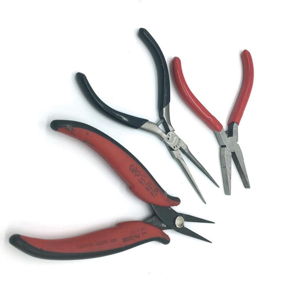
Pliers. I use three different sets of pliers every time I build: a flat long-nose variety with no teeth, a skinny long-nose with no teeth, and flat long-nose pliers with teeth.
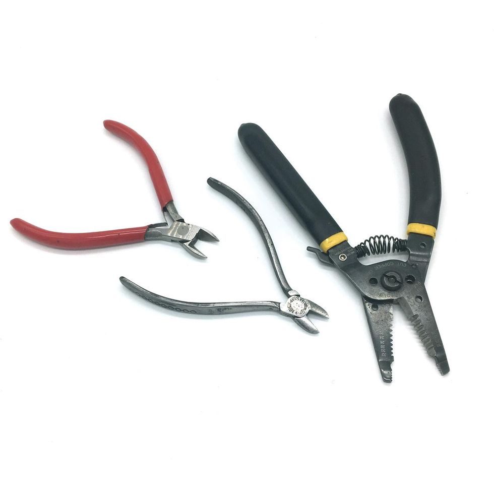
Wire cutters. For snipping wires and component leads. I tend to break wire cutter tips rather often, so I keep a few pairs around. I have a robust pair for cutting thick wires and metal, a pair of Xytronic AX103 Side Cutters for most everyday clipping work, as well as a fancy, sharp pair for more dainty work (like snipping leads off of PCBs).
Wire strippers. For trimming a small piece of each wire's outer coating (or "jacket") to expose the bare wire underneath. I like models like this Hanlong 20-30AWG stripper because they can strip a few different gauges of wire. "Self-adjusting" wire strippers like models from Irwin are also popular with some builders, though I find them a bit clunky to use. Note: When I'm not using wire salvaged from unused electronics, I prefer Teflon-coated wire because its outer jacket won't melt. One disadvantage, however, is that it's slippery as can be and nearly impossible to strip with the previously mentioned strippers. The tiny Jonard ST-550 works wonderfully with Teflon—and any other kind of jacket material.
A drill and drill bit(s). A powered hand drill will work fine, however I like to use a step bit like the Irwin 10231 Unibit self-starting fractional step drill bit so I don't have to change the bit every time I want to drill a different-sized hole. You might also want to pick up a center punch like those from Starrett, as well as a very small bit (1/16" or 1/8") that's made to go through aluminum or metal to drill pilot holes for the step bit.
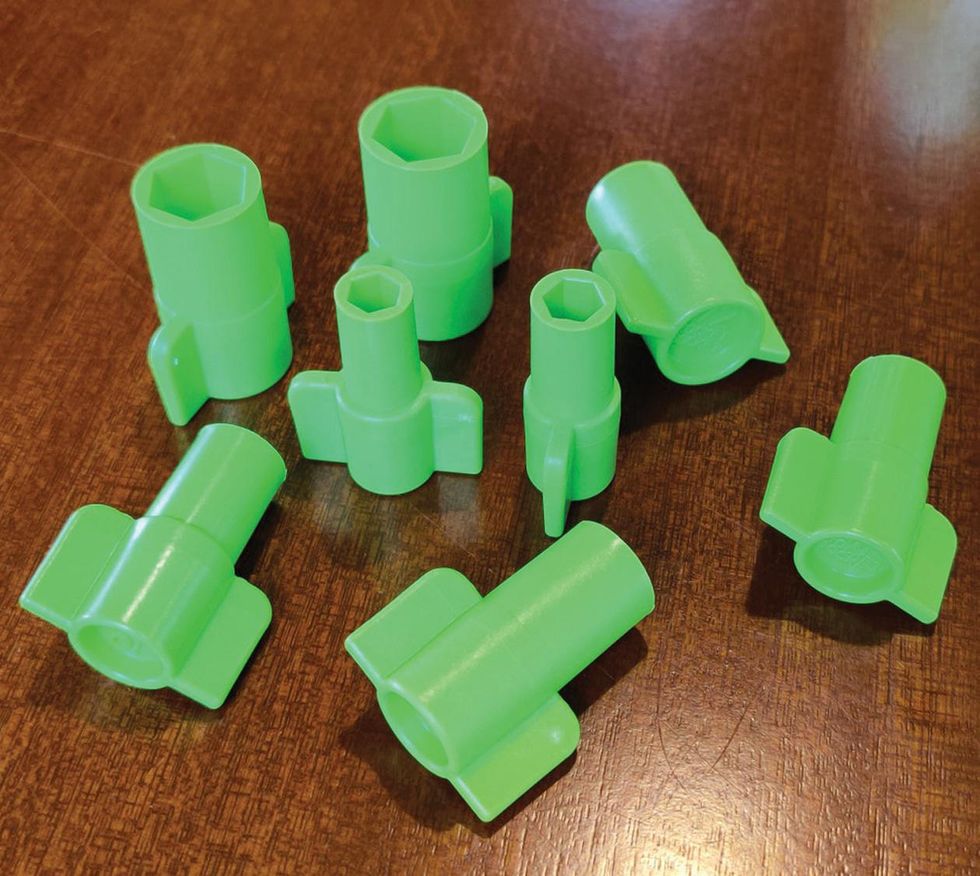
Rocket Sockets. They're not absolutely necessary, but they make installing jacks and hardware easier, faster, and safer. (Trust me—if you use pliers to tighten hardware, they're almost guaranteed to scratch the finish.) Rocket Sockets come in a set that includes all the sizes you'll need for building pedals.
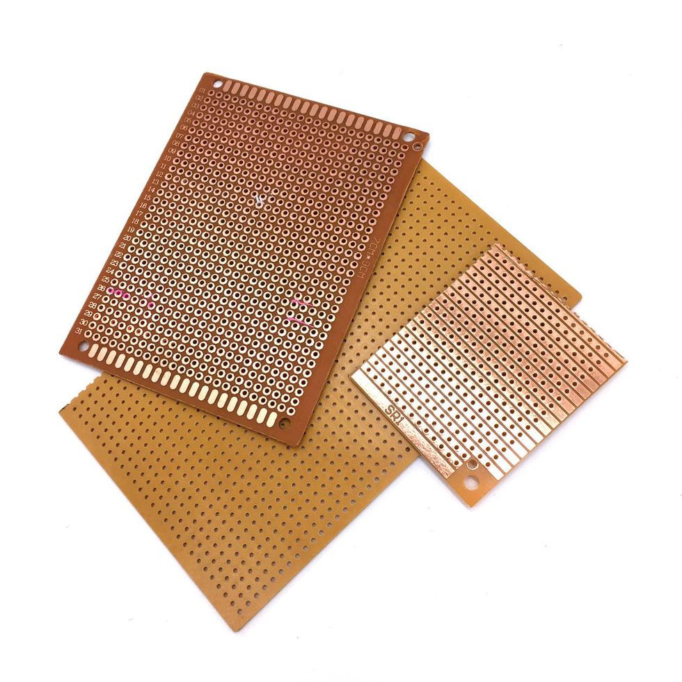
Circuit-board blanks. Two kinds of circuit-board substrate are most widely used for pedal circuits: stripboard (Veroboard is a common brand) has preprinted, horizontal copper rails, while perforated board (aka "perf board") looks similar but doesn't have copper rails (although some types of perf boards have copper tracing around each of the holes). Parts get directly loaded through the top of the board and are connected to each other on the underside. Note: Because we'll be wiring all our circuit-tester parts together directly (aka "point to point"), you won't need circuit-board material for the direct purposes of this article.
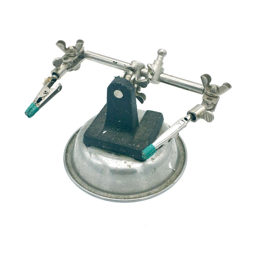
Helping Hands circuit-board holder. This affordable Radio Shack accessory is incredibly useful for holding boards and parts while you solder them.
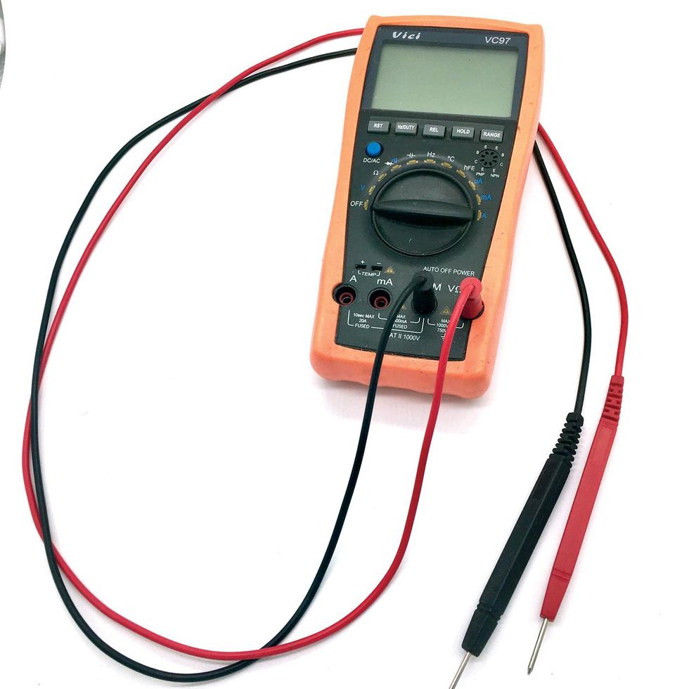
Digital multimeter. This isn't absolutely necessary for our project, but if you expect to keep building pedals it will definitely end up being the most important tool in your kit. Why? To avoid massive headaches at the end of your build, it's a good idea to get in the habit of testing all components before adding them to the circuit. A multimeter is also useful for checking continuity when you solder any two (or more) points together. Cheaper multimeters have a rotary dial that must be set to certain ranges of values to get an accurate reading. I prefer "auto-ranging" multimeters, which automatically test the exact value of an electrical component simply by putting a probe on each of its "legs." The affordable Vici VC97A works well in my experience.
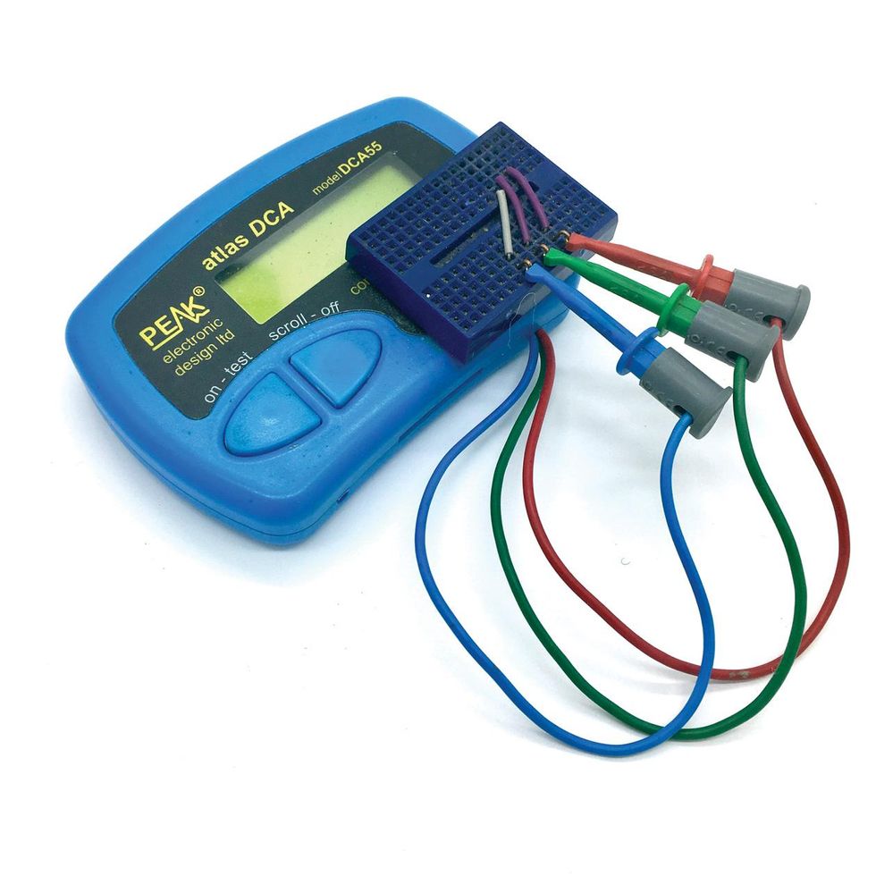
Semiconductor analyzer. The Peak Atlas DCA55 is one of the most-used tools in our shop. We use it to quickly and accurately measure transistors and diodes.
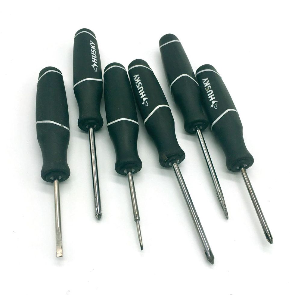
Screwdrivers. One standard-size flathead and one standard-size Phillips head are a must. I also use small screwdrivers for all sorts of things, including forming leads, pushing wires and components into place in tight spaces, and installing knobs. Radio Shack's RS Pro 6-Piece works just fine.
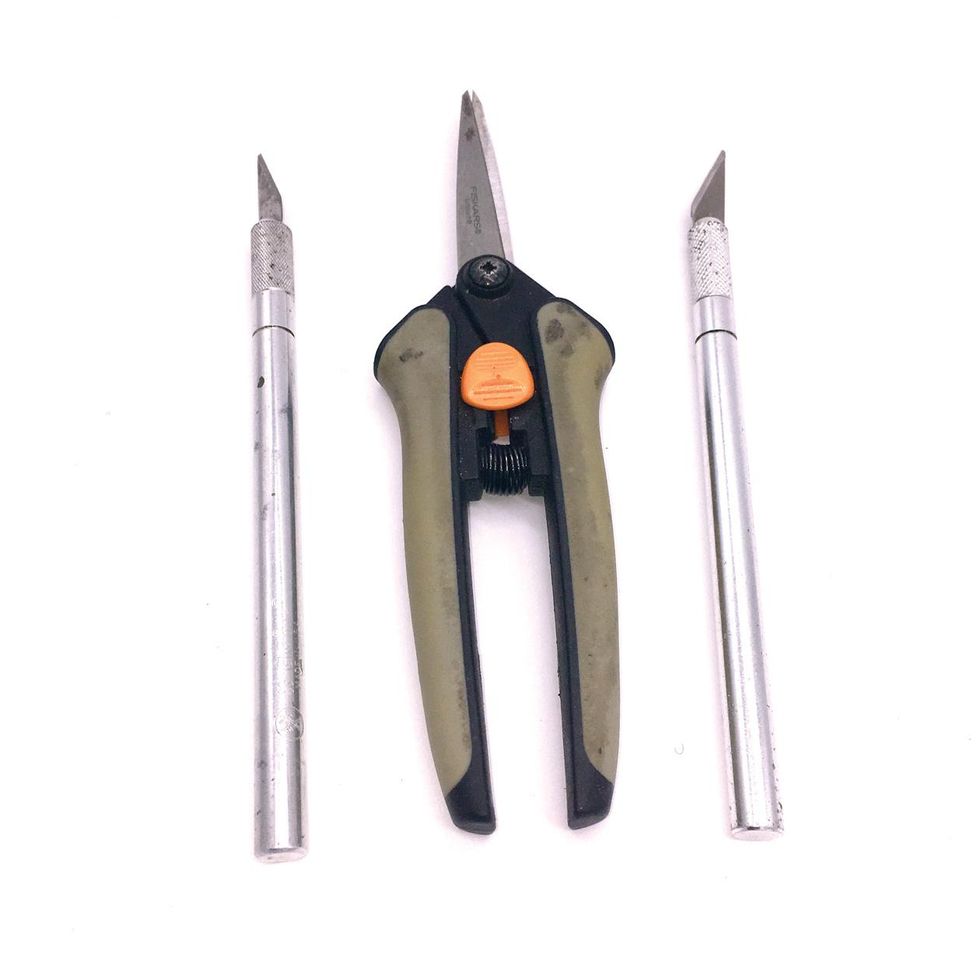
X-Acto #1 precision knife. I can't tell you how handy and necessary these are in every aspect of my creations!
Scissors. I like Fiskars Softouch Micro-Tip Pruning Snips, but just about any kind will work.
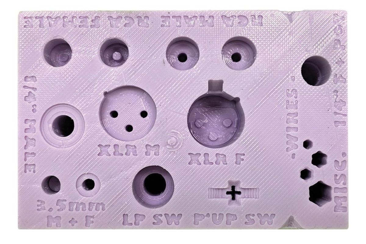
Radio Shack Hot Holder. This silicon block has molded compartments for holding everything from 1/4" jacks to footswitches, RCA and XLR plugs, and even pickup switches while you solder parts onto them. I initially balked at the price, but I have to admit I'm using it often.
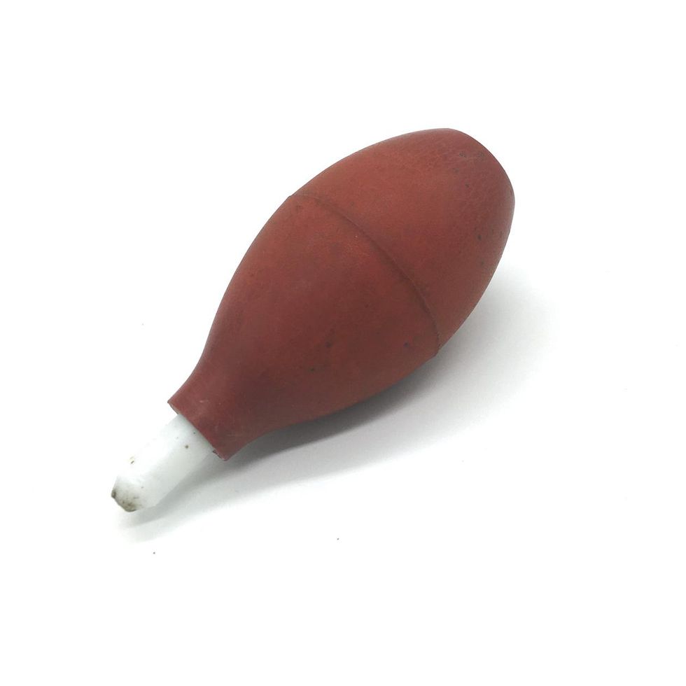
Desoldering bulb. Learning to desolder is an invaluable skill, as even the most seasoned pedal builders make soldering mistakes, and circuit-board pads and traces don't typically stand up to a lot of reheating while you try to do the job with just your soldering iron. A great way to practice is by desoldering components off PCBs from old or broken electronics. This is one of my favorite things to do, because you get comfortable with the process while saving a precious transistor or two from landfills. (There are other ways to desolder—some folks like to use a pump or solder wick. But I find the bulb to be the easiest, cleanest method, because you can apply different amounts of pressure to desolder more delicately.)
Parts Needed for Our Circuit-Tester Project
Hookup wire. 22- and 24-gauge stranded, pre-bond hookup wire is most common in pedal building, as anything thicker than 22 won't fit some hardware and some circuit-board holes, while anything thinner than 24 won't be robust enough. Jackets can be made of a few different materials— cloth-covered, polytetrafluoroethylene (Teflon)-coated, or the polyvinyl chloride (PVC) type most builders use. You can even get your preferred wire type in pre-cut, pre-"tinned" sets. However, knowing how to strip and tin wires (condition their tips for proper conduction—we'll talk more about this later) is a valuable skill, so I suggest using raw wire like the 24-gauge options available from LoveMySwitches.com.
DIY TIP: Although many pro pedal builders use a single color of wiring for their circuits, it's a good idea for new builders to purchase red, black, green, and blue wire, since, when you go a-hunting for layouts to build, you'll find that many use this color-coding scheme to denote positive, ground, input, and output wires, respectively—just as we have in our circuit-tester project.
Testing leads. Most pedal circuits have four wires coming off of the circuit boards: input (the green lines in our diagrams), output (blue lines), positive (red +9V lines), and ground (black). That means we'll need four testing leads. Because our circuit-testing box will be used over and over again, we should invest in quality, durable leads. I've found Mueller BU-2031-A-12-0 leads to be robust. (If you prefer longer leads, Velleman sets will work as well—but be sure to buy two packages, since each only comes with three.) The alligator-clip end of each lead hooks onto the input, output, positive, or ground wires of the circuit board we are testing, and the "banana-plug" end of each lead plugs into the corresponding banana post (see next entry for more) on the tester pedal.
You can also make your own leads to the exact lengths that are ideal for your workstation. If you go that route, Keystone Electronics 5046 alligator clips are a nice choice. Mueller even has a helpful video showing three different ways to attach an alligator clip to a wire. Meanwhile, AudioTrendsTV has a helpful video showing how to solder a banana plug. (Solder-less screw-on plugs are available, but in my experience the soldered variety are much more durable. If you buy the screw-on type, I recommend soldering the wire in for extra strength.)
You'll also need four banana plugs, and Mueller tapered-handle models are a good option. "Banana plugs" are single-wire electrical connectors used for joining wires to equipment, and the awesome thing about them is that the leads are removable, so you have a ton of options as far as tester leads go. Just be sure to buy the ones with an alligator clip on one end and a 4 mm male banana post on the other.
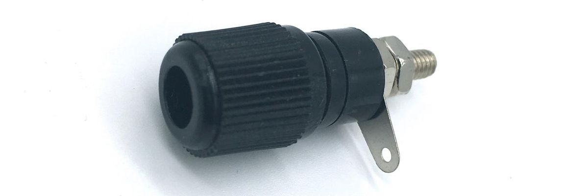
Banana posts. These are the jacks that the detachable test lead cables with alligator clip ends will plug into when the tester pedal is finished. They are also sometimes referred to as "binding posts" or "terminal binding posts," and you'll need four of these, too.
A metal enclosure. Aluminum enclosures are the most widely used for guitar pedals. For our project, I used an aluminum 1590BB-size enclosure I already had from a previous project. LoopholePedals.com is one of many places that offers drilling services for those who don't have the tools to do so themselves.
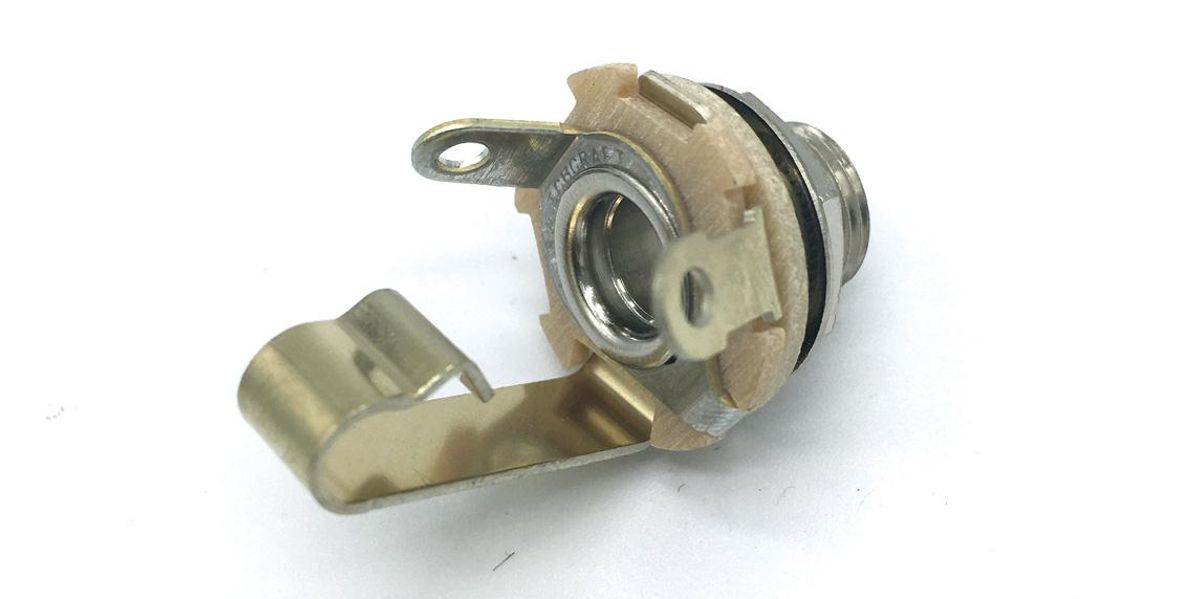
Jacks. Our test box has two 1/4" female audio jacks, as well as one 2.1 mm barrel power jack. I use Switchcraft #11 monoand #12B stereo jacks, and Lumberg or Mouser DC jacks.
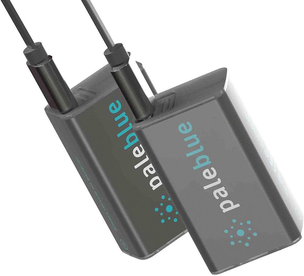
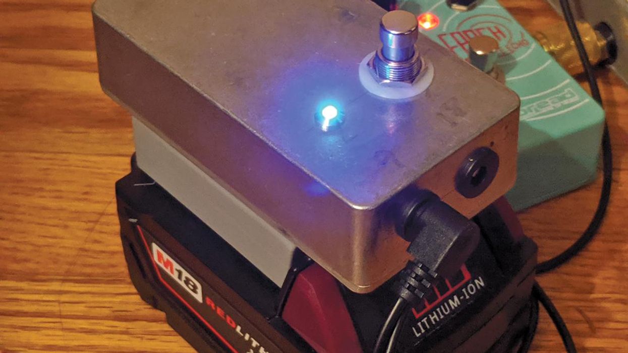
9V batteries. Batteries are terrible for the environment, but we sometimes need them for circuit testing. I always plug into a circuit powered by just the battery at first. Once it powers on properly, I switch to a 9V DC center-negative power supply for further testing. Rechargeable 9V batteries help ease environmental impact and are easy to charge via USB cable. They don't seem to hold a full 9V charge, but since I only use them for the initial test, the 8.6V I've measured from their leads is good enough.
• 9V battery clip connector (center-negative) power-supply cable. To connect the rechargeable battery to the tester pedal's power jack without having to remove the back of the enclosure. (Don't worry—if you prefer a regular 9V connector, I'm including the wiring scheme for that, too.)
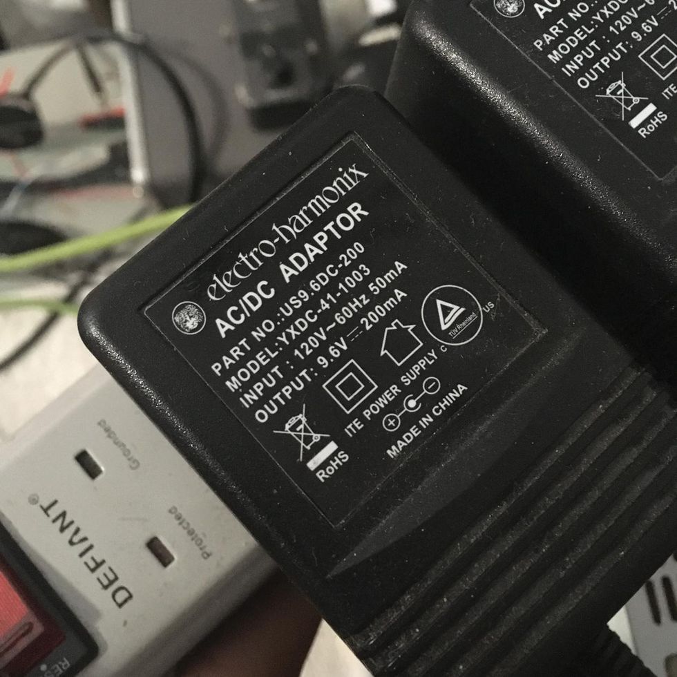
9V, center-negative regulated power supply. Clean power is crucial for a pedal, but especially so when you're testing it. I use the Electro-Harmonix US96DC-200BI, because the power seems to be clean and less noisy than others (I've tried more than a dozen brands).
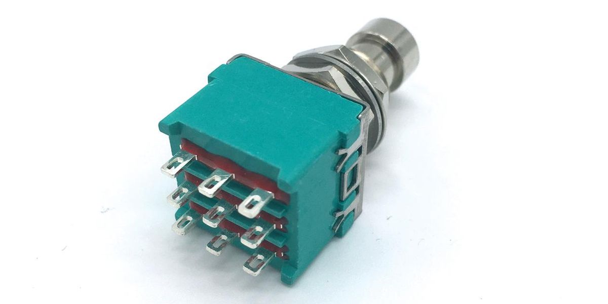
A latching 3PDT (triple-pole, double-throw) switch. It can be either a footswitch or a toggle.
Note: Speaking of switches, it's a good idea to research how they work if you haven't already done so. Understanding how the internal mechanisms connect and how the connections change as the switch is engaged makes the whole off-board-wiring experience much less daunting. BeavisAudio.com has some very useful information on the subject, and DIY Guitar Pedals has an informative video, too.
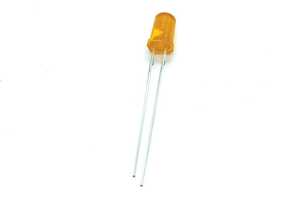
Bypass LED (light-emitting diode) and LED holder. Pick any color you like. 5 mm and 3 mm models seem to be most popular for pedal building.
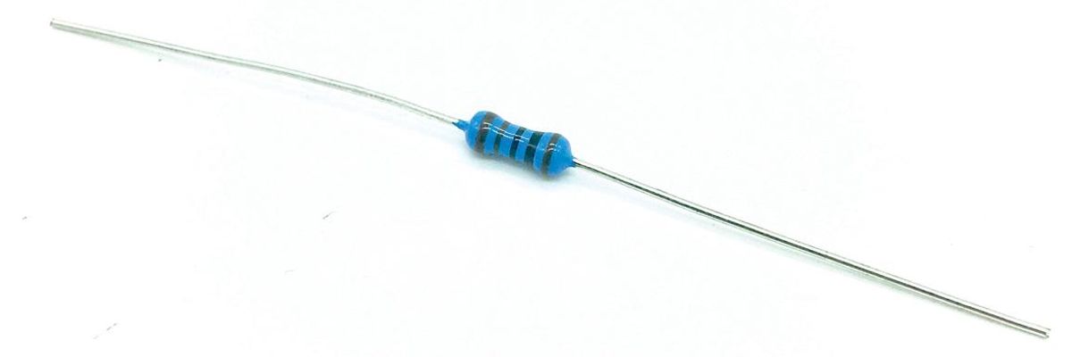
1kΩ 1/4-watt resistor. LEDs are quite robust, but they need a resistor attached as a current limiter so they don't blow. You can use a 2.2k or 4.7k resistor too. The higher the resistance, the dimmer the light will be.
The Pedal Builder’s Best Friend: How to Build a Circuit Tester
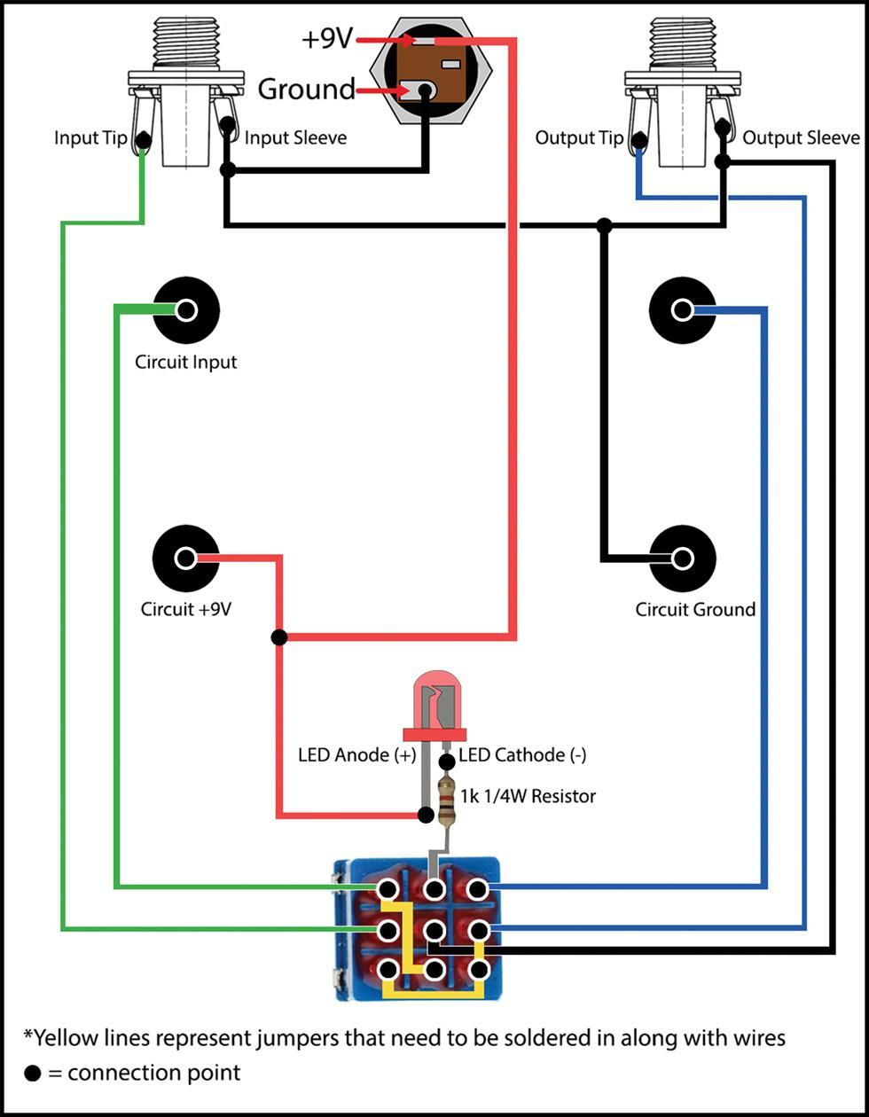
Okay, I think I've hyped this killer tool enough. Unless you need to take a sec to go online and consult our Soldering 101: A Step-by-Step Guide, let's build this thing! Here's a wiring diagram.
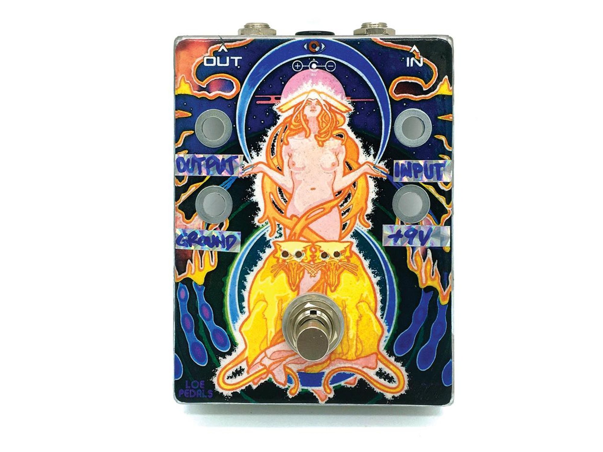
1. Drill the housing. Before we can start wiring, the enclosure needs holes drilled out to accommodate the input, output, and power jacks, as well as the LED and bypass (on/off) switch. If your enclosure didn't come with predrilled holes, you can drill for the jacks on the housing's top or sides, whichever you prefer. I prefer power and audio jacks on top, with the power jack in the center and the input and output jacks opposite each other whenever possible.
We also need to drill four holes for the banana posts that will be connected internally. As mentioned earlier, every circuit you build will have input (green diagram lines), output (blue), positive (red), and ground (black) wires that need to be connected to your tester pedal. Note: The enclosure I'm using already had four holes on top, so my layout reflects this. You might choose to put the banana posts on the side(s), top, or someplace else. That's the beauty of DIY!
I have a mantra: Measure three times, drill once. You can use a Sharpie or other marker to mark the spots you want to drill. Hit each mark with the center-punch tool, then drill pilot holes. Once pilot holes are drilled, you're ready to install your step bit in the drill. (Reminder: The step bit is marked on its side with size values so you know where to stop drilling for the desired hole size.)
PRO TIPS: Some DIY sites have drill guides you can download and print out to make the process easier, but it's still good to learn how to do it manually. Also, Barry Steindel from GuitarPCB.com has a great video tutorial on how to drill pedal enclosures with a hand drill, and DIY Guitar Pedals has one for those who prefer a drill press.
IMPORTANT: Most component and hardware manufacturers publish data sheets listing characteristics and specifications—including physical measurements—for their products. It's a good idea to consult the data sheet for each of your components prior to drilling so that you know how many steps of your step drill bit (or which sizes of standard drill bits) to use.
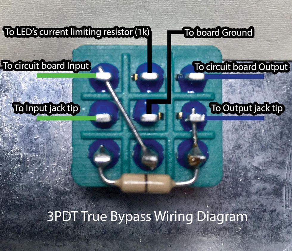
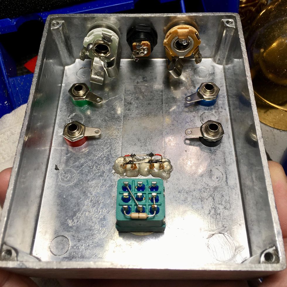
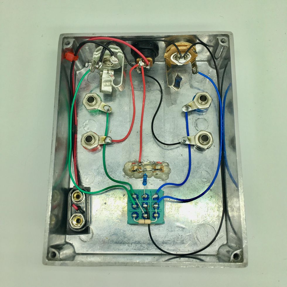
2. Prepare the switch. To start with, let's connect a couple of "jumpers" on the underside of our 3PDT switch so it functions as a "true bypass" switch (which provides the most transparent signal for circuit testing). This can be done a few different ways, but my preferred method is to add a wire between lugs 1 and 8, as well as lugs 6, 7, and 9. (As you see in the image below, some builders use a 0Ω resistor rather than a bare wire for the jumper between lugs 6, 7, and 9. It's perfectly fine to use a simple wire for this, which is why I didn't include a second resistor in the list of necessary parts for this build.) For now, only apply solder to the three bottom lugs, since the two other lugs (1 and 6) also need to accommodate the wires we'll add in later.
Note: Although you can use regular hookup wire, I use snipped-off leg pieces from resistors or other components for these jumpers.
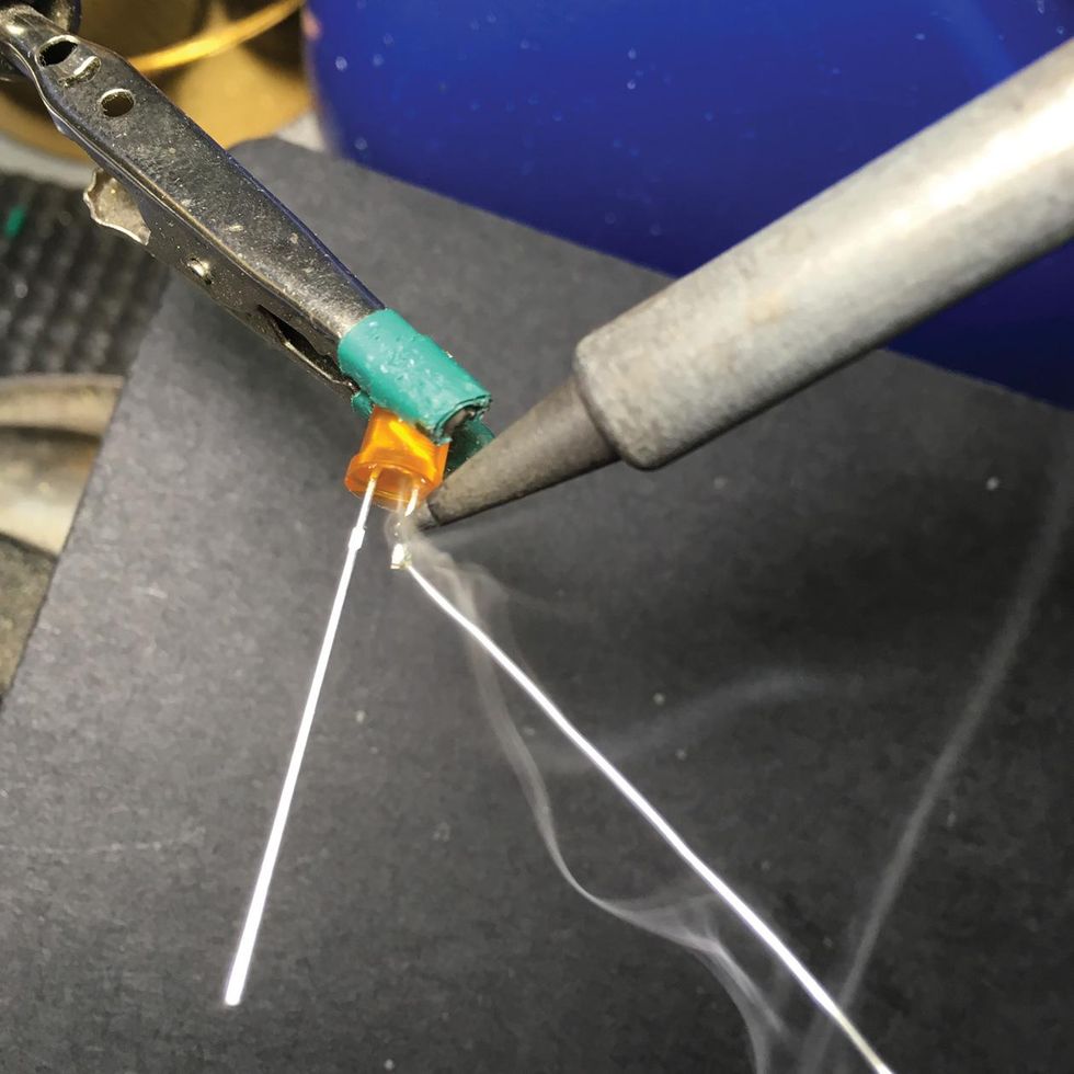
3. Prepare the LED wiring "harness." First, we're going to trim the LED's ground (cathode) lead, which is the shorter leg. Then we'll "tin" the trimmed end by touching the soldering-iron tip to it, applying a tiny dab of solder, and then sliding the iron tip back and forth along the ground lead for a brief moment until the solder melts and the entire surface of the leg appears shiny. Why? Tinning limits corrosion of the metal leads and helps components fuse together better at solder joints. The LearnElectronics channel has a useful tinning demo video.
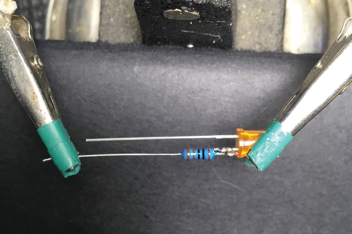
Next, cut all but a 1/4" off the 1kΩ resistor's legs, then tin the short end. Put the LED's body into one of the "hands" of the Helping Hands tool, with the legs facing inward, then put the long lead of the resistor in the other "hand," with the snipped, tinned leg facing in. Push the "hands" together until the two short, tinned leads of each component overlap. Touch the soldering-iron tip to the junction for a brief moment, add a dab of solder, and remove the iron's tip once the solder has pooled and settled in, nice and shiny. A shiny solder joint is generally a solid solder joint.
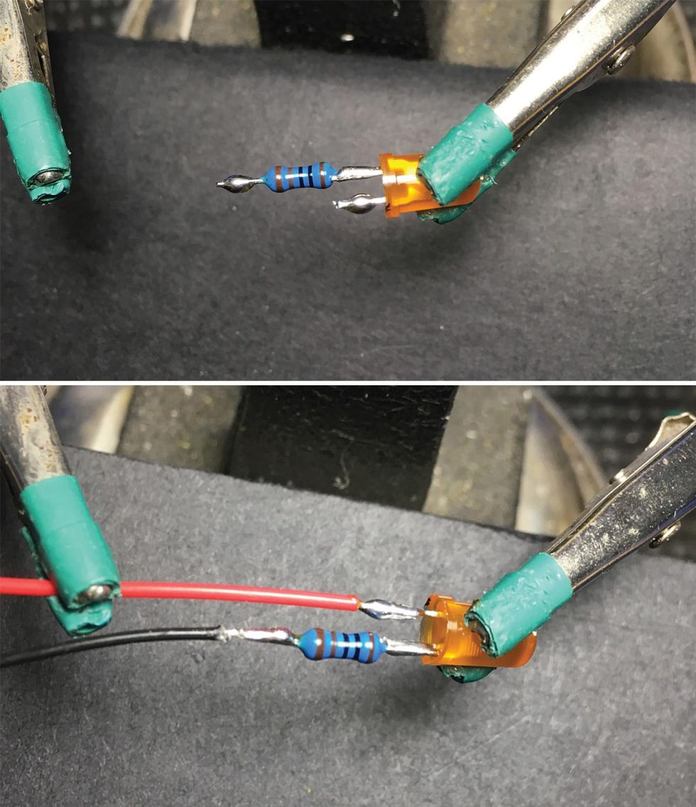
The leftover leg on the 1kΩ resistor is sometimes long enough to be soldered directly to the footswitch, as is the case here. But if your LED hole is further away than ours, you'll need to add a wire. To do this, trim the resistor's other leg to 1/4" and tin it. Next, strip and tin a piece of black hookup wire long enough to reach from the 3PDT switch to the LED hole. Now snip the LED's longer leg (the positive or "anode" lead), again to a 1/4", and tin it. Cut another wire long enough to reach from your power jack to the LED hole, then strip and tin the ends. Load the stripped, tinned wire into the other Helping Hands holder and push the "hands" together until the end of the wire overlaps the LED's anode. Solder them together so that the solder has pooled and settled, nice and shiny, as before.
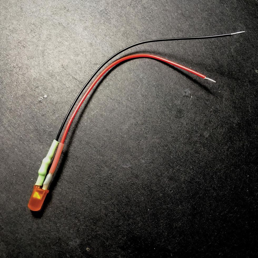
Although it's not crucial, you can encase these two solder points in 1/8" shrink tubing for extra stability, neatness, and to help keep the joints from shorting out against each other or the enclosure (don't use electrical tape instead—you'll regret it!). The YouTube channel MrJustDIY has a helpful video on how to do so. The most important thing is to make sure your solder joint is good before you cover it. I recommend testing for continuity with a multimeter before adding the shrink stuff.
4. Install the enclosure's hardware. With our footswitch and LED harness ready to go, we're set to use those Rocket Sockets (or other appropriately sized socket wrenches) to attach the footswitch and the input, output, and power jacks.
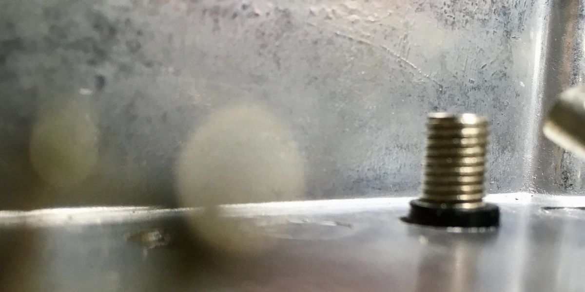
As for the banana posts, they have a hollow, threaded column with an insert at the top that accepts a banana plug. IMPORTANT: You don't want that metal post touching the metal enclosure at all. Thankfully, banana posts come with plastic insulators that go around the post, ensuring that they don't short-out the circuit. Install the banana post from the top, as shown below.
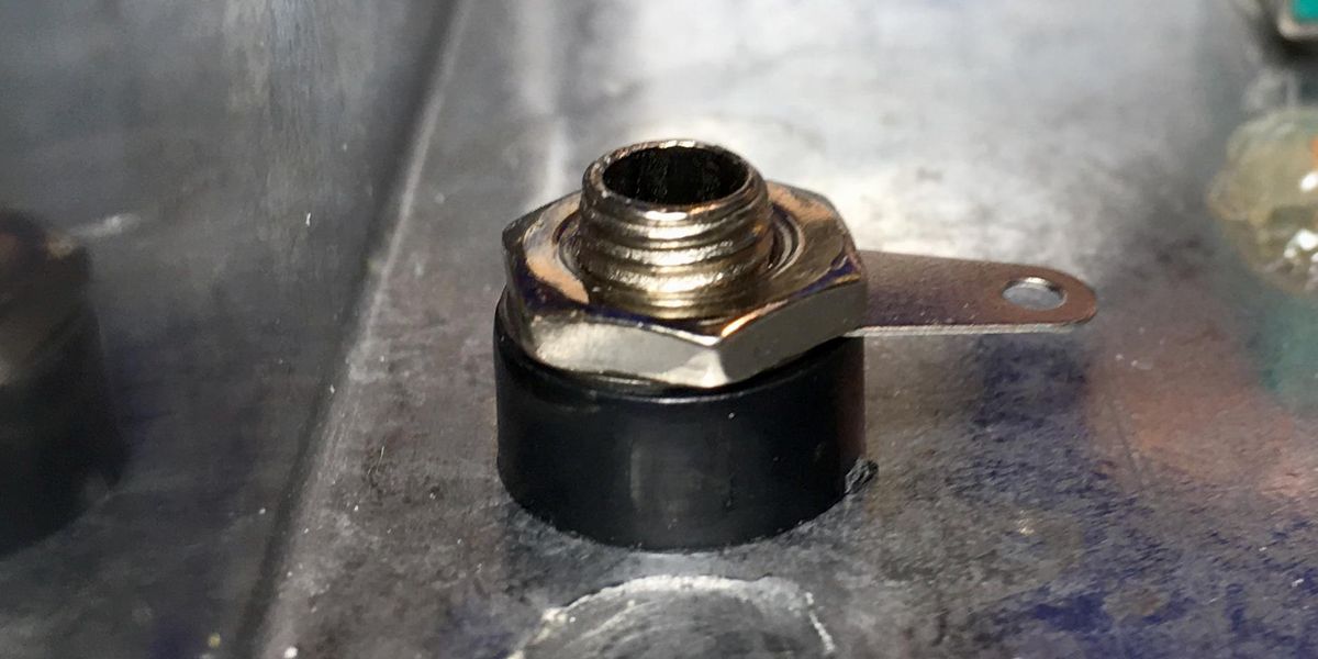
Next, put the plastic insulator cylinder over the post, followed by the little tab thing, then the nut. Tighten it snugly, but be careful not to crack the plastic insulator by over-tightening.
Note: If you're wondering why my LED isn't installed in a holder/bezel, it's because my recycled enclosure already had an LED glued in. It's much cleaner and sturdier to use a holder or bezel, however. If you aren't using shrink tubing around the joints, it's imperative that none of the bare leads touch the bezel (if it's metal) or the enclosure. We don't want it to short out—or worse, to blow! When you install your LED, make sure the positive and ground wires are properly oriented before you push the LED into the holder. Point the positive wire toward the power jack, and gently bend the ground-plus-resistor lead toward the bypass switch.
5. Wire and solder the circuit. Measure the distance to and from each of the points that need to be connected, as per the wiring diagram—and, ideally, in the same colors. Be sure to add a couple extra millimeters on each wire, as it's really annoying to get in the building groove only to realize a wire is too short! Next, use your wire strippers to strip 1/4" of the plastic jacket off the ends of each wire. As you tin each wire end, keep in mind that PVC jacketing melts very easily, so don't apply heat too long or you'll end up with a mess. The tinned wire ends should look shiny all the way around, like they're encased in chrome.
TECH TALK: Let's discuss 1/4" jack anatomy for a second. We are using two types—our output jack is mono and has two tabs, while our input jack is stereo and has three tabs. Turn the input jack sideways, and you'll see three protective wafer layers separating three metal terminals on the jack. These are commonly referred to as the "tip" and "ring." The ring is above the second wafer. The tip is the terminal above the first wafer, just above the base of the jack itself. The ground tab, or sleeve, is connected to the center part of the jack at the base, floating above all three wafers, and does not have a protective wafer on top. The output jack will only have two protective wafers separating the two metal conductors (the ground and tip tabs). If you decide not to add the battery snap internally, you could use two mono Switchcraft jacks as you would not need the additional ring connection used for turning the battery on and off.
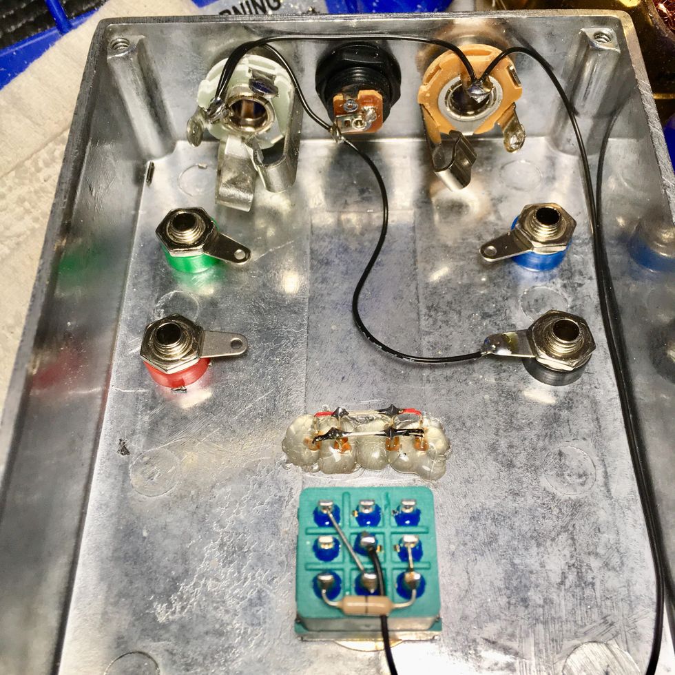
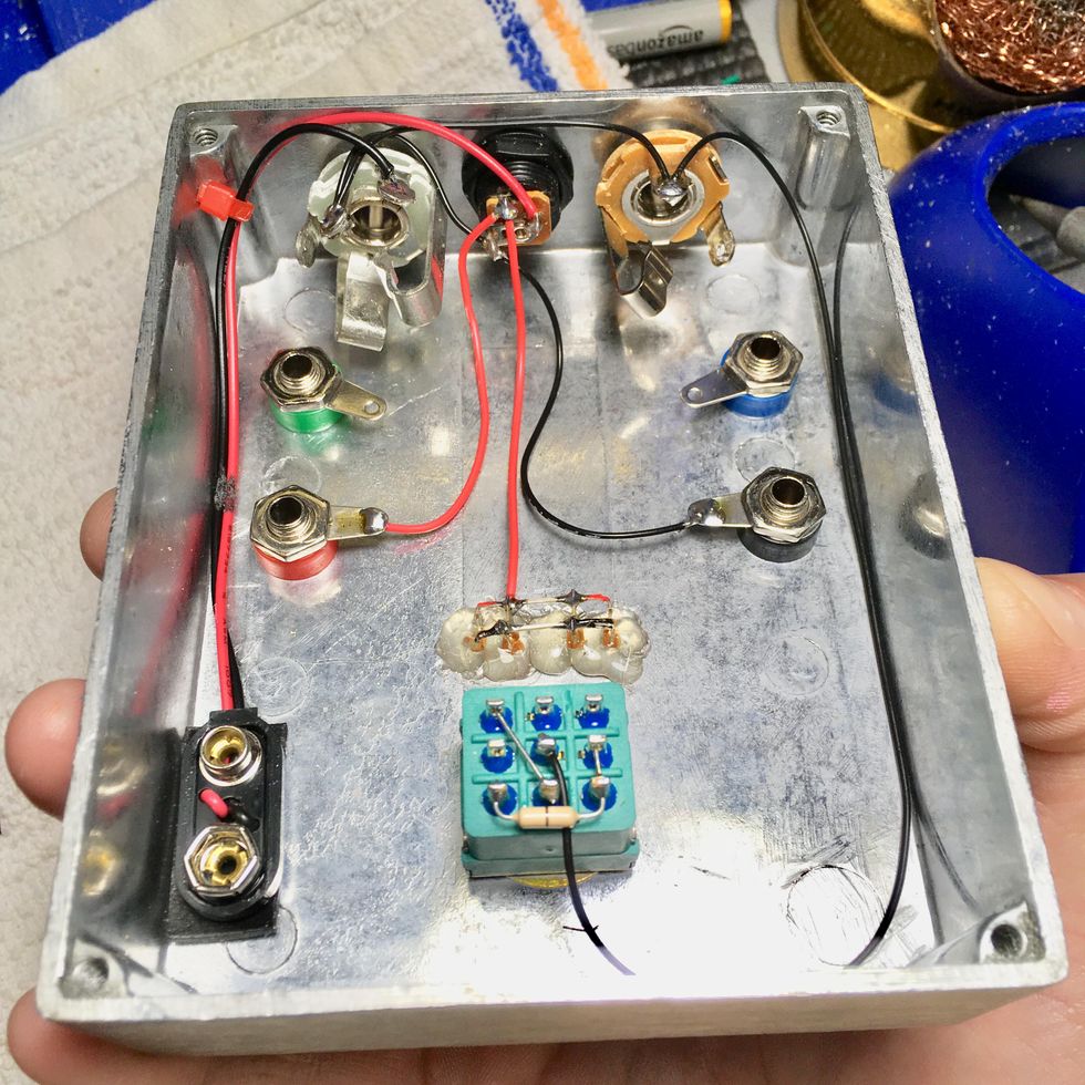
Okay, let's insert and solder all the ground wires first. I always use black wire to avoid confusion and match the diagram. Again, make sure each solder joint is shiny before you move to the next one. Also, be sure none of the wires are too taut, or they're likely to eventually come loose.
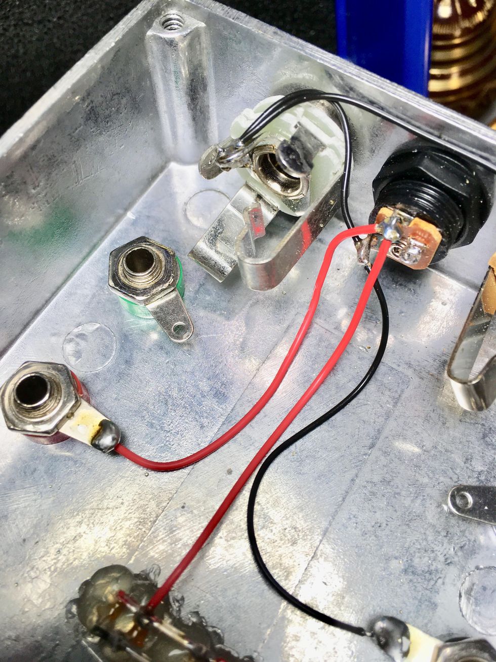
Next, I like to insert and solder the red, positive-connection wires. This is easier than ground wiring, because it only connects in two spots and one wire is already attached to the LED's positive leg. Note: Although the diagram looks like only one wire is attached to the power jack, a separate red wire will go from both the LED and the positive banana post to the power jack's sleeve pin (see photo). Both wires should fit there fine, but don't solder that joint until both wire tips are gently squeezed into the hole.
If you want to install a battery snap, do that now. Strip and tin the ends. Note: Soldering the red wire to the power jack's one remaining empty tab prevents the battery from losing juice—but only if you remember to unplug your 1/4"instrument cable from the input when you're not using the box. Plugging into the input connects the battery. Unplugging disconnects it.
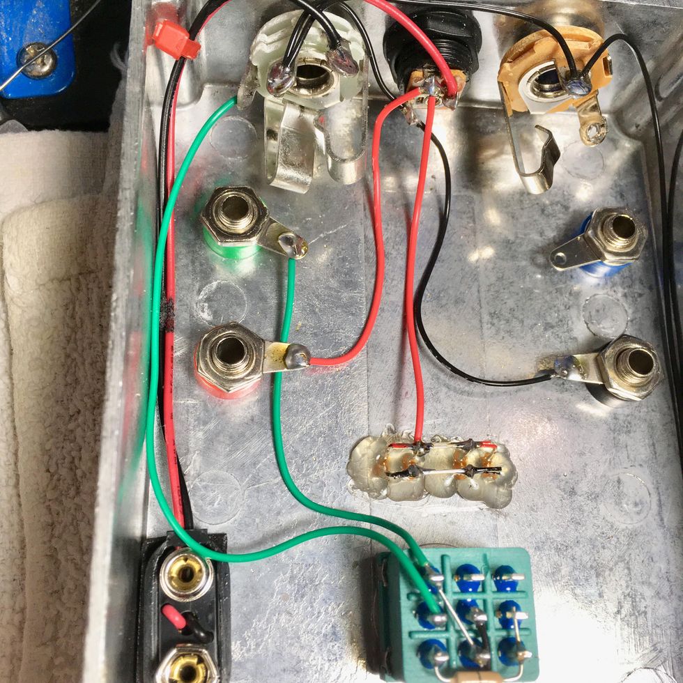
Now let's install our input (green) wires. One goes from the tip of the input jack to lug 2 (middle lug in the leftmost column) of our 3PDT switch. The other green wire goes from the input banana post's tab to lug 1 (top left) on the switch, along with one end of the jumper.
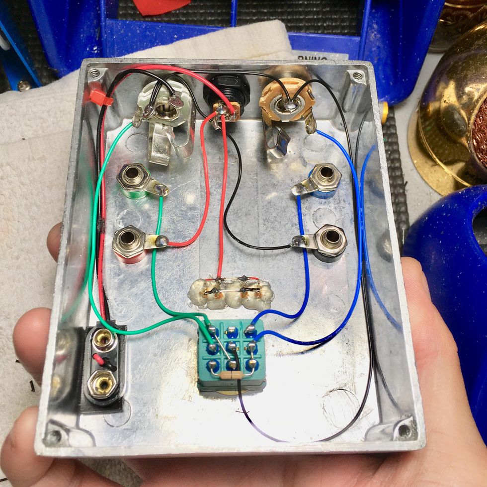
To connect output (blue) wires, route one from the tip of the output jack to lug 8 (middle of rightmost column) on the switch. The second blue wire goes from the output banana post to lug 7 (top right) on the 3PDT switch.
Lastly, connect the LED's ground leg to lug 4 (top row, middle) on the footswitch. Remember, my example looks a little different and your ground will be the black wire coming off the LED.
6. Test the circuit with a multimeter. Set your meter to "continuity" mode (consult its manual if you're not sure how to do so), touch one of its probes to a solder point in our circuit tester, then touch the other probe to the solder point on the other end of that particular connection. For example, touch one probe to the solder point located on the input-jack tip, and touch the other probe to lug 2 (middle lug in the leftmost column) of our 3PDT switch. Your meter should beep or light up if you have a solid connection. Once you've tested and found continuity in all our circuit tester's connections, you'll know it's ready to start testing guitar-pedal guts.
Using your new circuit tester is really easy. First, make sure it's got power from a 9V battery or an adapter, then simply plug your guitar into the tester's input jack, and your amp into its output. Then attach each of the circuit-tester's four leads (input, output, ground, and positive) to the corresponding wires on the circuit board you're building or testing. In other words, connect the alligator clip from your new circuit-tester's input lead to your project pedal's input wire, connect the alligator clip from the tester's output lead to the output wire on your project pedal, and so on for the positive and ground connections, as well. That's it! Engaging the bypass switch will connect the circuit. Bypassing will yield a clean guitar signal.
Now you have a simple, easy way to test all the wonderful DIY effects you'll be building. Congratulations! Hopefully, this article has shined a little light on the processes involved with learning to wire a pedal. Moreover, I hope you had as much fun building it as I did! In fact, I'd love it if you'd share your tester-pedal shots with Loe Sounds (@loesounds) on Instagram Stories.
I would be remiss if I didn't acknowledge Steve Daniels and the crew at Small Bear Electronics for their dedication to providing education and reliable supplies to the DIY pedal community for 22 years. At publication time, Small Bear had announced it would soon be closing its doors. Pedal builders everywhere will miss them dearly, and we can only hope someone comes along to carry the torch and fill the big void Small Bear will leave.
DIY Pedal Sites You Should Check Out
- The DIYStompboxes.com forum is my go-to. It's where I met invaluable mentors like Pink Jimi Photon (of PJP Effects), and Dino Tsiptsis and Phil Moulder, whose Dead End FX site has intermediate to advanced projects and PCBs, including some pretty rare stompbox gems.
- The Effects Layouts blog features some of the tidiest PCBs and layouts for perf boards based on popular guitar-pedal schematics.
- The Tagboard Effects blog has Vero-type stripboard layouts for popular pedal schematics, as well as a helpful forum.
- Madbean Pedals hosts a forum with lots of really nice, helpful folks. They've also got downloadable PCB layouts, sell quality PCBs, and some of the most well-documented projects out there, from beginner to advanced level.
- Beavis Audio Research has a whole bunch of great information, including well-laid-out, easy-to-read diagrams.
- R.G. Keen's Geofex. Keen is practically the godfather of DIY guitar effects. Most of us couldn't be doing what we are doing without what we have learned from this invaluable site!
- RunOffGroove.com is an old-school site with great, bare-basics schematics and articles.
- ElectroSmash.com is a treasure trove of projects, schematics, component information, and detailed breakdowns of popular pedal circuits.
- MusicFromOuterSpace.com features mostly DIY synth stuff, but I learned so much from their articles. Ray Wilson's contributions to the DIY community are too many to count.
- Experimentalists Anonymous allows you to make your own layouts from dozens of schematics.
- DIY Layout Creator offers freeware for designing layouts and is great for learning.