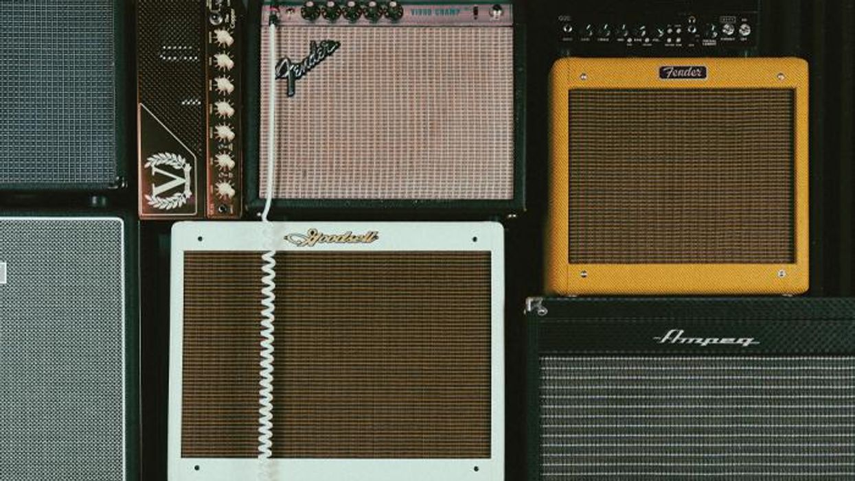

Famous tube amps from companies like Fender, Marshall, Vox, and others have come to define the sound of virtually all electric-guitar music. To varying degrees, we know that these amps sound different from each other—and we might even know some basic specs, like what kind of tubes different models use, and maybe some details about stock speakers. But it can be hard to understand some of the finer reasons why these amps sound different from each other.
Once we plug in our guitars, all sorts of electrical processes happen as our signal makes its way from the input jack on through the unique set of electrical components that give each amp its signature sound and on through to the speaker. What goes on inside of our amp once we've plugged in our guitar? And what makes one amp louder than the next?
Although there's much, much more to cool amp tones than could possibly be discussed in an introductory piece like this, there are a lot of basics in common between the various brands and types of circuits, particularly with regard to how tubes (preamp and power), watt ratings, and speakers work. Because of this, we can learn a lot from a more specific example. To that end, let me tell you a little story about one of my favorite amps.
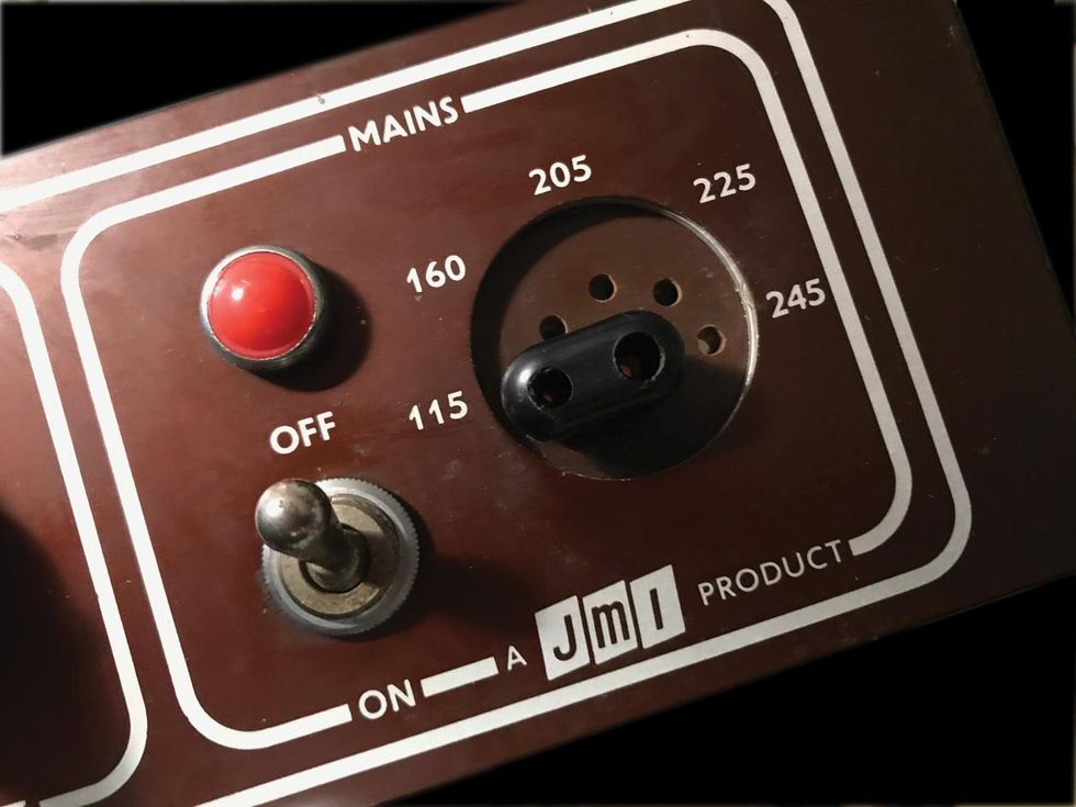
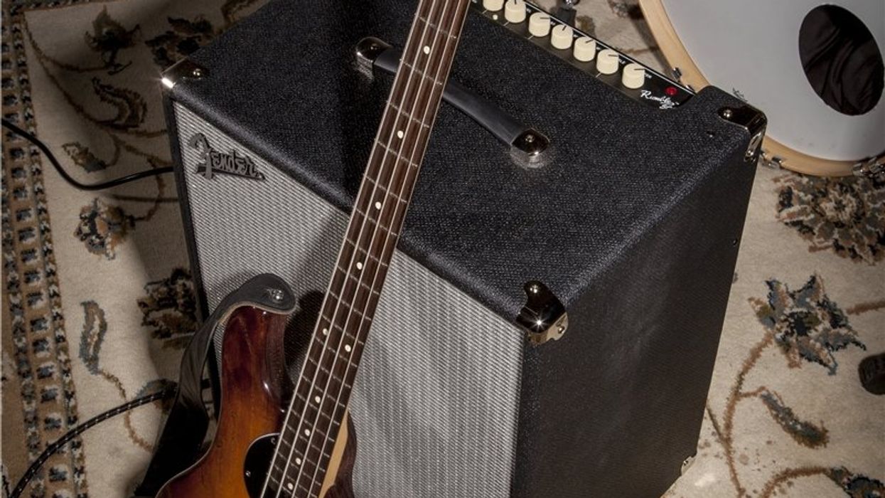
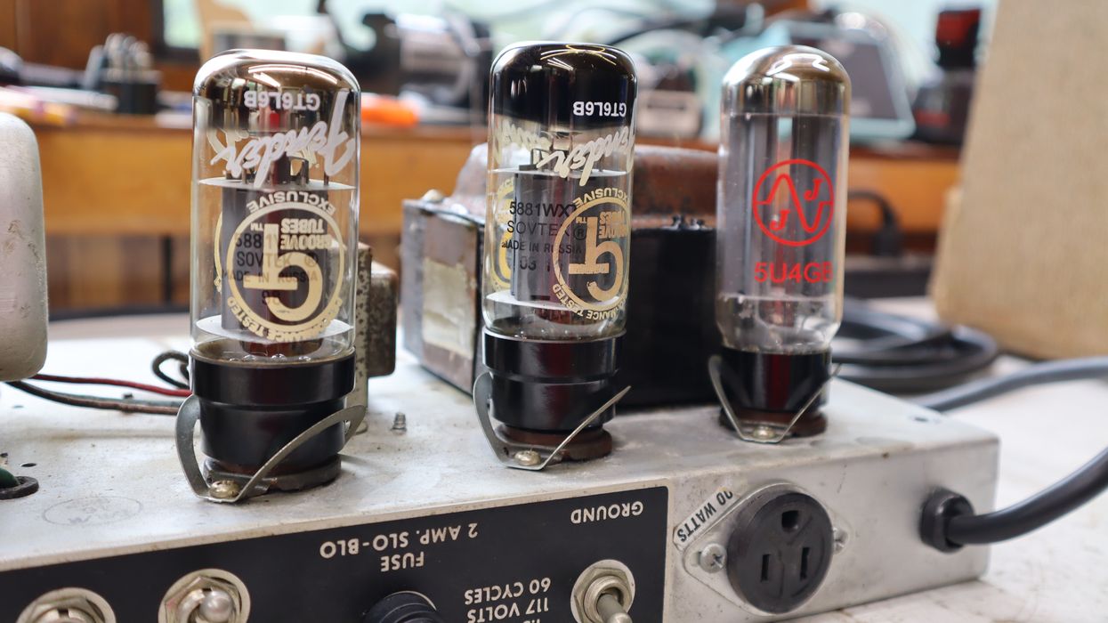
Dan Formosa found his 1960 Vox AC15's international voltage selector was incorrectly rated, and avoided overloading the amp's original tubes after doing an extensive online search and calculations.
I recently had a revelation about a beautiful, fawn-Tolex-covered, circa 1960 Vox AC15 that I bought from a dealer in the U.K. (full disclosure: many years ago) and finally got around to restoring. That meant replacing the electrolytic capacitors before daring to turn it on, since they have a life span. The AC15's international voltage selector on the far right of the control panel has settings for 115, 160, 205, 225 and 245 volts. I expected my U.S. wall voltage to be a few volts higher than its nominal 120, but still within reason for powering the amp at the 115 setting. However, the readings I got when checking the internal voltages were sky high. Its original Mullard EL84 power tubes were being overloaded at almost 17 watts, while 12 watts is the designated maximum and 14 watts would be pushing my luck. A few Variac voltage experiments over the next few days, along with some obsessively created Excel calculations and charts, verified that a wall voltage of 105 would be more appropriate. A week of deep Google searches and an eventual exclamation of "Thank you online discussion boards!" uncovered the problem. While there were no markings on my AC15's power transformer, chassis photos of two exact same amps and transformers showed the power transformer input terminals labeled as 105, 145 (not connected, like on mine), 160, 205 and 245. Despite the control panel's graphics, the amp never had a 115 volt option. That setting connects to the power transformer's 105 volt terminal. Furthermore, the 225 and 245 selections were both connected to the 245 terminal. Apparently when Vox printed that panel in 1960, they were just kidding.
My near-miss chance of seeing the power tubes glow like it's Christmas led me to think about the journey electrons take through an amp, combining forces emanating from your wall and your guitar to power the speaker. And what it means to overload a tube, as I came close to doing. Did you ever wonder why a single EL84 tube is rated at 12 watts, but powers a 5 watt amp? Or why two EL84s power a 15 watt amp? And why, when adding two more to the set, four will produce 30 watts? Let's explore watts and electrons, and investigate how exactly they travel in your amp, from power tube to speaker.
Identifying the limit of a tube or a speaker in watts means defining the maximum amount of energy per second it can safely handle.
Power In Vs. Power Out
When discussing power and watts, keep in mind that your tube amp isn't primarily functioning as a guitar amplifier. It's more of a space heater that produces sound. Here's a question that Steven Fryette, of Fryette Amplification and Sound City Amps, is frequently asked: "How is this a 30-watt amp when it says 100 watts on the back?" The short answer: An amplifier is filled with components that consume power that never gets to the speaker. Power transformers get warm, the pilot light and heating filaments within the tubes suck up a lot of juice—the preamp tubes and power tubes are approximately only 50 percent efficient— and there's heat being produced by the output transformer. Power-wise, the speaker operates mostly as a heat sink. A tube amp is therefore far less efficient than you might guess. More than 99 percent of the incoming power ends up as heat. Less than 1 percent exits as sound. To help understand how all that power turns into hardly any sound, we'll discuss EL84 tubes—although any power tube could serve as an example, since all are guided by the same physics.
At the center of the tube, preamp tubes included, is a cathode, a small tube that emits a cloud of electrons when heated. The plate—that's the gray or silver metal wall that you see when looking through the tube's glass—contains a high-voltage, electron-attracting DC charge. The signal from your pickups is sent to the preamp tube's grid, and eventually to the power tube's grid. The grid is a wrap of wires within the tube surrounding the cathode. The grid regulates the flow of electrons traveling from the cloud to the plate. In a class A or class AB amplifier (more on that to come), the grid allows electrons to flow even when at rest, or "idle," meaning electrons are on the move even with no guitar signal on the grid. Start to play and an increase and decrease of electron flow perfectly mirrors the guitar's signal. Electron flow is also known as current.
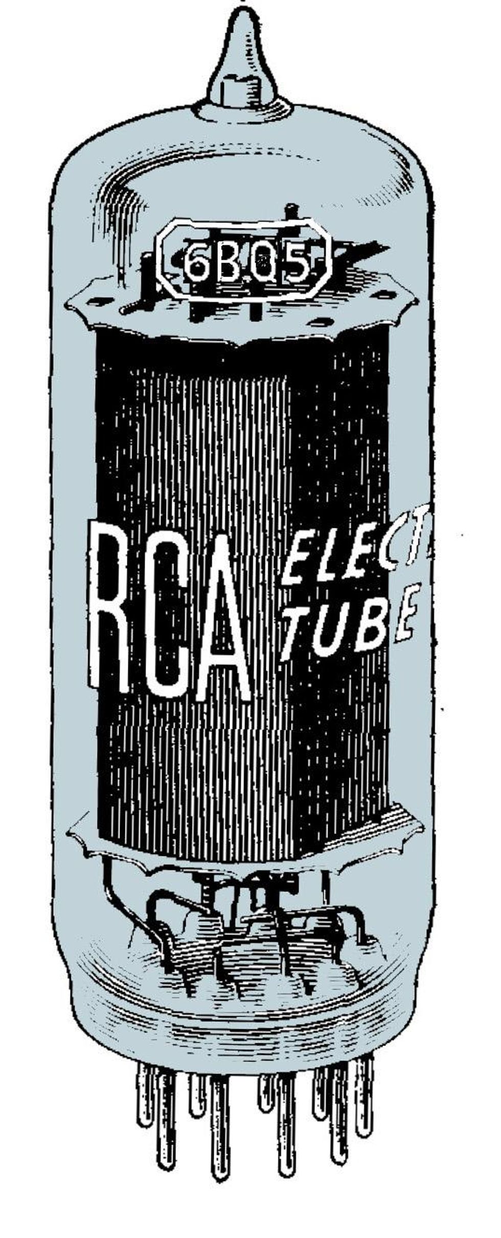
An RCA 6BQ5, aka EL84, tube consumes 12 watts, but like all power tubes it produces about half of that in power. The EL84 is a staple in the world of power tubes, typically associated with Vox and Marshall amps.
So, what's a watt? A watt is a rate of power—one joule per second, with a joule being a unit of energy—and can be calculated by multiplying volts times amps. Therefore, a watt is a measure of energy per second. Identifying the limit of a tube or a speaker in watts means defining the maximum amount of energy per second it can safely handle. Given the calculation for wattage (volts x amps = watts), you can see that increasing voltage, amps, or both will increase wattage.
Defining that power relationship one step further, what's an amp? It's short for "ampere" (not, in this case, "amplifier"). An amp holds the "per second" dimension of time seen in watts. In a classic plumbing analogy, volts are equivalent to water pressure, while amps measure the flow rate of that water. Too much of either will electrically flood your tube or speaker.
Water flow and pressure may not be a great analogy, because what really results when a tube or speaker becomes overloaded with watts is too much heat. But to complete the water analogy, resistance (or the related term "impedance" … we'll get to that, too) is like reducing the diameter of the water pipe. It's therefore fair to think of a tube as an electron pump, continually circulating electrons.
The Secret Life of Watts and Tubes
Electrons bombarding the plate too quickly will cause it to glow red and radically shorten the life of your tubes.
Receiving the up-and-down voltage waves of a guitar signal, the grid controls the flow of electrons, holding some back or unleashing them in accordance with whether you're delicately picking or bashing. The high level of positive, electron-attracting DC voltage on the screen grid and plate elements determines the amount of electrons pulled from the cathode. (Essentially determining how loud your amp gets.) Tubes, however, have limits, both on the rate at which the cathode can produce electrons and on the rate at which the plate will accept them.
Try to attract more electrons than the cathode can emit and you'll reach saturation. Flood the plate with too many electrons and you'll exceed its maximum dissipation level, overheating the tube. Set the grid's bias voltage too negative and you'll reach cutoff, a point where the negative swing of the guitar signal's sine wave will suddenly prevent any further electron flow from the cathode.
Picture your guitar's signal as a simple sine wave—a pure A440, for instance. Turning the volume up high can produce too much voltage swing on the tube's grid, and then on the plate, to be handled cleanly. The result you hear will be the sound of a sine wave being abruptly flattened at the high and low points of the wave. You may be perfectly happy with that level of distortion. But what if we overload a tube in a less friendly manner?
Class Acts
Amplifier circuits are designed to use tubes in different ways. The circuits we are primarily concerned with in tube amplifiers are class A and class AB. However understanding classes A and B helps to explain class AB, a hybrid of the two. So….
How Class A Circuits Catch a Wave
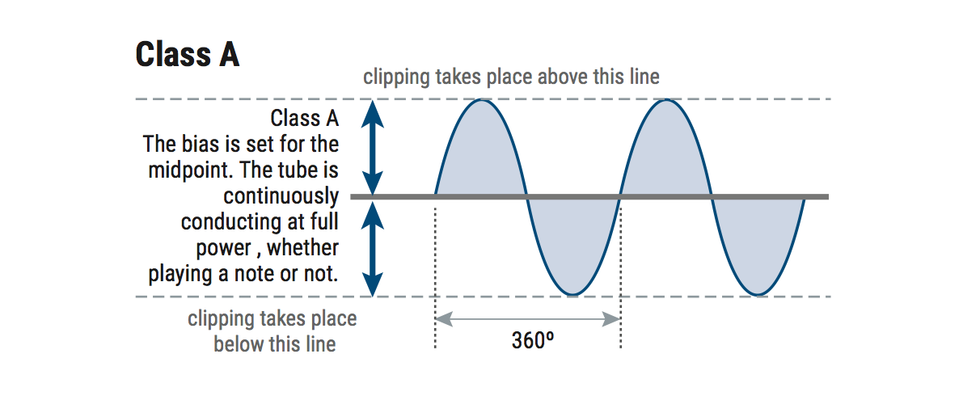
In a class A amp circuit, the power tube constantly carries the entire signal. So, a tube operating in a class A design is always conducting at maximum dissipation—full on—whether you're playing guitar or not.
Amplifiers with one power tube—single-ended amplifiers—operate in class A. That one power tube carries the entire 360-degree span of the sine wave, measured along a horizontal axis in degrees. The bias is set so that the amp idles along the vertical (Y-axis) center of the sine wave, evenly positioned between the peaks and valleys. That means the tube is always conducting at maximum dissipation—that it's always on full whether you're playing or not. When playing, the guitar signal creates peaks and valleys in the sine wave. Many, actually. The peak of the sine wave increases current flow; the valley of the wave reduces it.
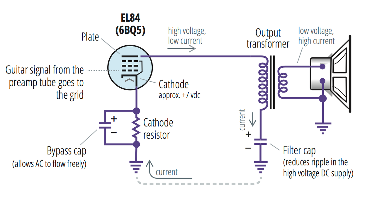
This flow diagram shows how an EL84's power comes from electrons flowing from ground, through the tube, through the output transformer, and back to ground. It's a cycle.
An EL84 power tube can produce approximately 5 watts in a single-ended amp. Therefore, you would think two EL84 tubes would produce 10 watts. And that's true: Power tubes can be configured in parallel to double the output power. Consider, for instance a Gibson GA-9 amp, which puts two 6V6 tubes in parallel. It's done, but not often. Why? Because a class AB configuration can produce more than double the power output from two power tubes. But before we get to that….
Make Some Noise, Class B
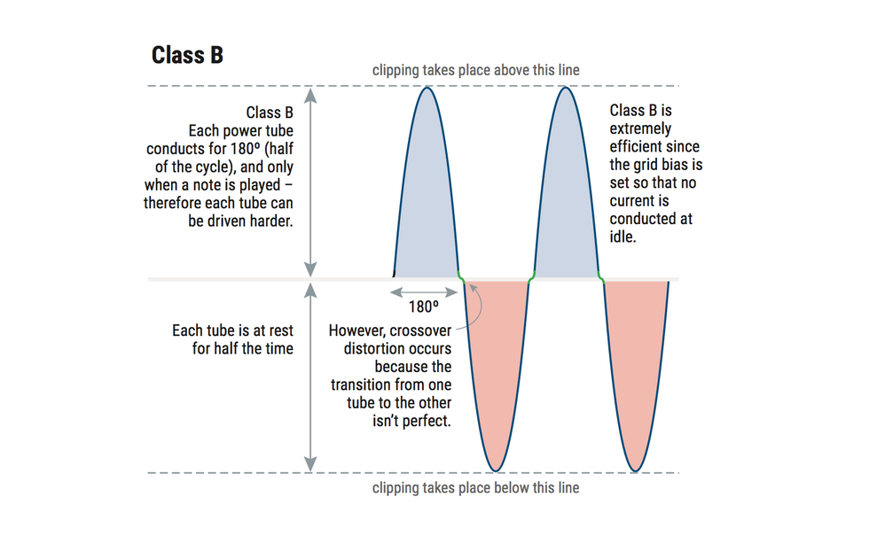
In a class B amp, each tube carries exactly half of the signal. Because the transfer of the signal from one tube to the other is never perfect, it creates crossover distortion.
In a class B amp, two power tubes share the sine wave. One conducts the first 180 degrees of the wave, and the other conducts the second. It's a push-pull arrangement. Unlike in a class A amp, each tube is at work only half the time. This allows each tube to be pushed further, into higher amplification, during the time it's conducting. To take advantage of that rest time, voltages at the plates can be higher, as can the signals going into the power tubes' grids. If a single EL84 tube can deliver 5 watts in class A, it can deliver twice that in class B during its half of the sine wave. Two tubes, therefore, will deliver four times the power, in theory. In practice, it may be less. Another advantage of a class B circuit is that at idle, neither tube is conducting, so it's a very efficient configuration for power consumption and for tube life.
All of that would be great for a guitar amplifier if the transition from one tube to the other occurred instantaneously. It doesn't. As the sine wave moves from positive to negative and back to positive, there's a delay—a misalignment in the transition between the tubes. The delay creates crossover distortion. Steven Fryette's description: "Crossover distortion can create a fizzy sound in the amplifier, [because] one tube is turned off before the other is fully turned on." And that, in a nutshell, is why class B isn't a common option for guitar amps. Enter class AB.
Class AB—Double the Fun
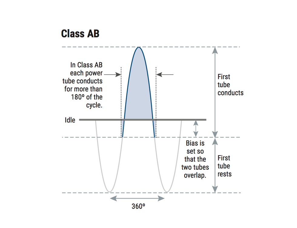
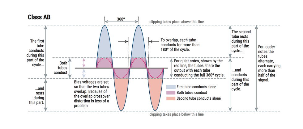
A class AB circuit solves the crossover distortion problem by having two (or four) tubes overlap responsibilities. Each tube, or each pair of tubes, carries more than half of the 360-degree signal of the sine wave.
In a class AB circuit, two power tubes share the responsibility of conducting the sine wave, similar to class B, but with some overlap. The tubes are set up so that one starts conducting before the other finishes, so each tube conducts for more than 180 degrees of the sine wave. This eliminates issues with the transition from one tube to the other. While not as powerful or efficient as a class B circuit, it's close—and the reason two EL84 tubes can deliver 15 watts in class AB amplifiers.
But if one EL84 delivers 5 watts and two can boost that to 15 watts, why do four only deliver 30 watts? Because in an AB amplifier with four power tubes, the tubes work together in two pairs, with each set delivering exactly twice the power of one tube. In a Vox AC30, for example, each pair of parallel EL84s creates 10 watts. It then puts the pairs in class AB configuration, doubling the output of a two-power-tube-amplifier, like the Vox AC15, from 15 to 30 watts. The diagram here explains that in greater detail.
In a class AB circuit, each power tube get a chance to rest half the time an amp is operating. Because of that, power tubes can be pushed harder when they are conducting.
The Output Transformer Takes Sides
The output transformer converts high voltage and low current on the primary side—which is to say, the tube side—of the circuit to enough low voltage and high current on the secondary—or speaker—side to drive a speaker. An output transformer's primary side is rated in ohms, but ohms in impedance, not resistance. The difference is that impedance takes into account that an AC signal is involved, since resistance will vary significantly depending on the frequency. (Frequency is the number of oscillations per second in the AC signal.) The impedance determines the rate of flow of electrons, with higher impedance being more restrictive.
The Alliance: Speakers and Transformers
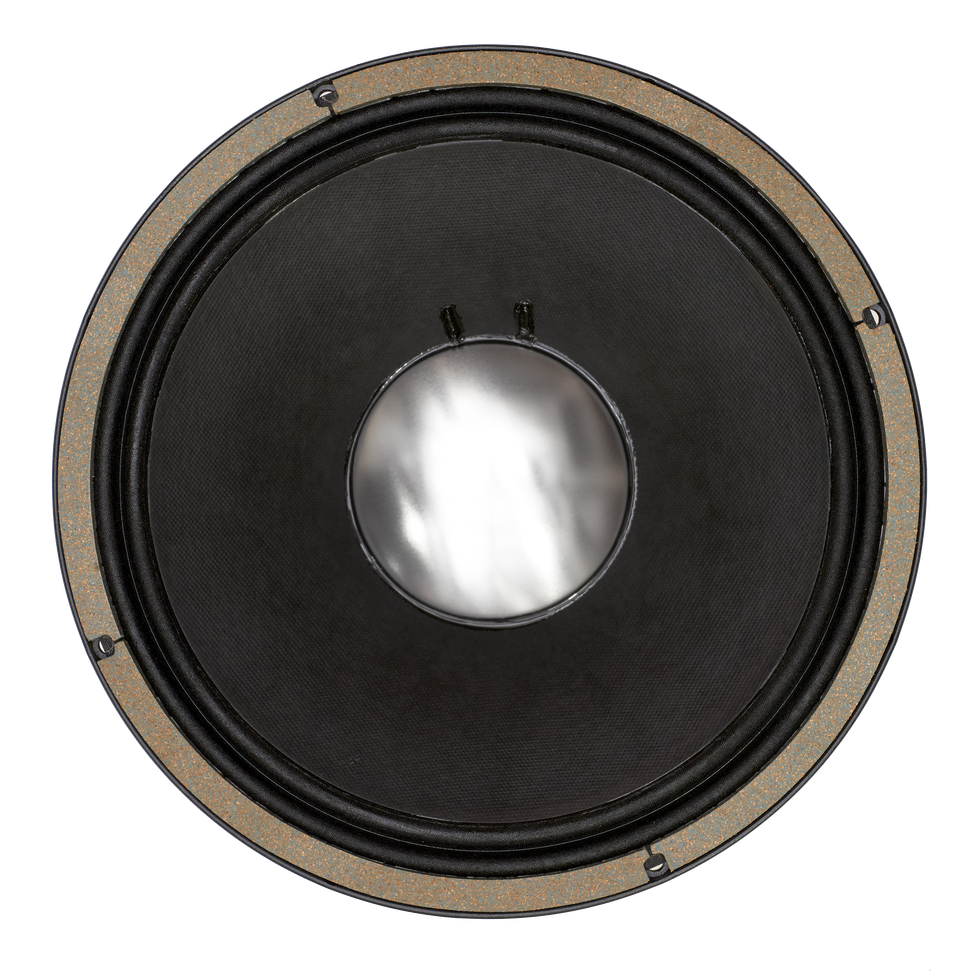
It's important to match a speaker's impedance rating with the output transformer, because, interestingly (and maybe somewhat surprising), the impedance on the primary side of the output transformer will change based on the impedance of the speaker you connect on the secondary side. If you connect a speaker rated at half the impedance—for example, put a 4-ohm speaker in place of an 8-ohm speaker—the impedance seen by the tubes will be cut in half. Twice the current will flow on both the tube side and the primary side. The 4-ohm speaker will be louder but can lead to trouble. Your power tubes or output transformer can overheat. It's not risky, however, to put a 16-ohm speaker in place of an 8-ohm speaker, although it won't sound as loud. In discussing this with John Paice at speaker manufacturer Celestion in Ipswich England, he had some simple advice: "Don't do it." Best practice is to match the speaker with the output transformer.
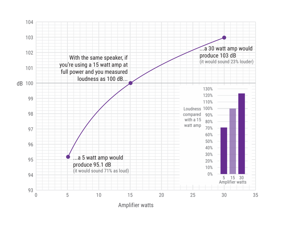
Doubling the wattage of a 15-watt amplifier will increase perceived loudness by 23 percent, not double it. And so, a 5-watt amp would sound 71 percent as loud as a 15-watt amp.
In terms of guitar amplification, we measure—and hear—power and loudness along a logarithmic curve. Doubling the wattage going into a speaker results in a 3 dB increase. At 3 dB more, we're not doubling loudness. It's approximately a 23 percent increase in volume. You can therefore expect a 30-watt amplifier to sound 23 percent louder than a 15 watt amplifier. And a 5-watt amplifier will be 71 percent as loud as a 15-watter.
If mixing speakers in a multi-speaker cabinet, be conscious of each speaker's impedance rating (they should match) and also of each speaker's sensitivity rating, found on its spec sheet. (Sensitivity is usually determined with a microphone connected to a sound level meter placed one meter in front of the speaker. The result is expressed in dB.) Advice from Celestion's Paice: "If mixing speakers, try to keep their sensitivity rating within 3 dB of each other, because any more than that will become noticeable. The more sensitive speaker will dominate the blend."
What’s with Speaker Wattage
A large speaker magnet does double-duty. It will hold the voice coil more firmly, producing more bass. It also acts as a larger heat sink. A Celestion G12M rated at 25 watts incorporates a 35-ounce magnet. A G12H at 30 watts incorporates a 50-ounce magnet. "A bigger lump of metal is better at dissipating heat, so you can put more power into it," explains Paice. In addition to heat, too much power into a speaker can potentially result in too much cone movement, damaging the cone and its surround, and possibly resulting in failure. Nonetheless, a 50- or 100-watt Marshall amp pushing a set of four Celestion 25-watt speakers is a classic sound, employed by Hendrix, Clapton, Page, Slash, and many other guitar heroes. Running multiple speakers in a cab reduces the punishment any single speaker must take. And, of course, using a high-power-rated speaker with a low-power amp can also net good sonic results. "Some people think that you have to put as much power into a speaker as it will take," says Paice, "but you can get lots of breakup with a high-power speaker using just a lunchbox-size amp."
Bactrian Amps, Anyone?
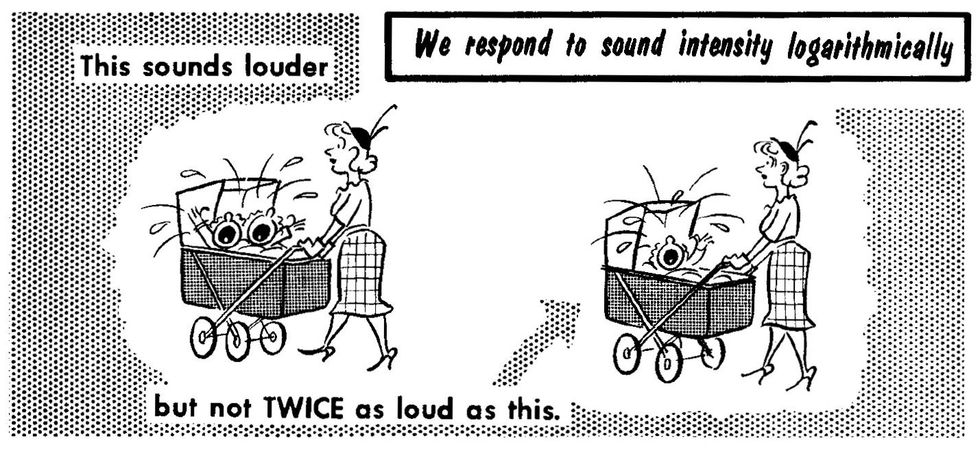
You may be thinking, okay, if doubling watts into a speaker doesn't double the loudness, I'll just use two amplifiers. No, no, no—the same principles apply. Since we hear logarithmically, two 15-watt amplifiers will give you the same output as a single 30-watt amplifier. It's an increase, but not double.
I like going back to the classic 1959 publication on sound and amplification, Basic Audio, Vol 1. by Norman H. Crowhurst. He shows an illustration of two crying babies in a twin stroller, comparing their loudness with one crying baby in a stroller. Two babies are louder, but not twice as loud. So while that physics phenomenon may not work to your advantage as a guitar player, think of how grateful you would be if you were the parent of twins.
Peeling the Onion
Let's take a deeper look inside tubes, output transformers, and speakers.
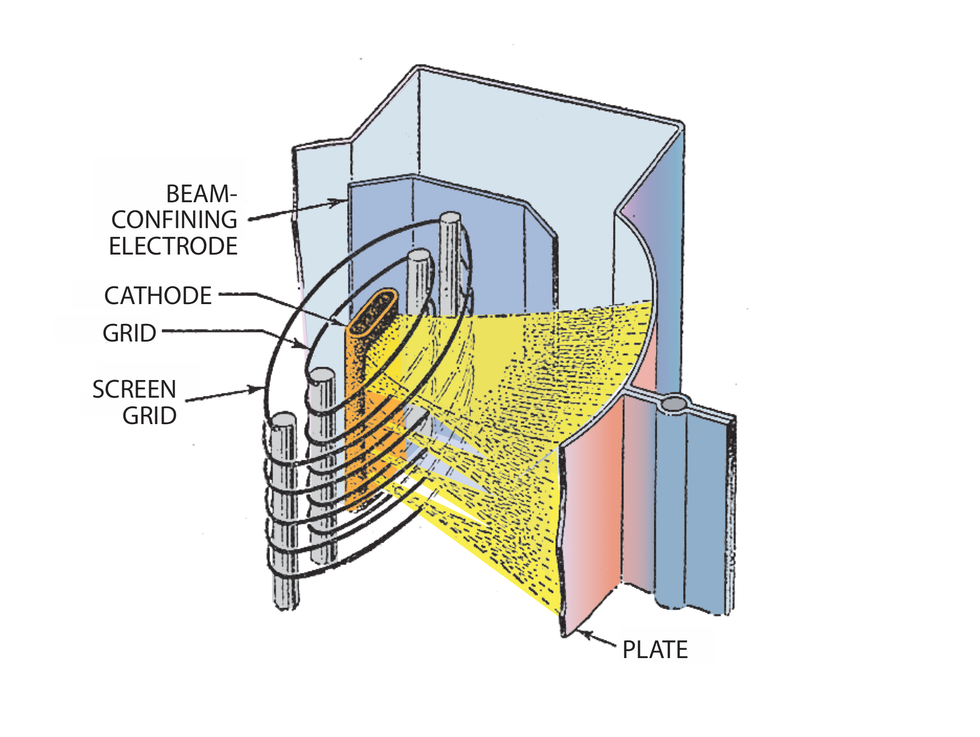
This diagram shows the ve components within an EL84 tube. Note the minute distance between the grid and cathode. That's the open range for negative-charged electrons.
Under the Glass
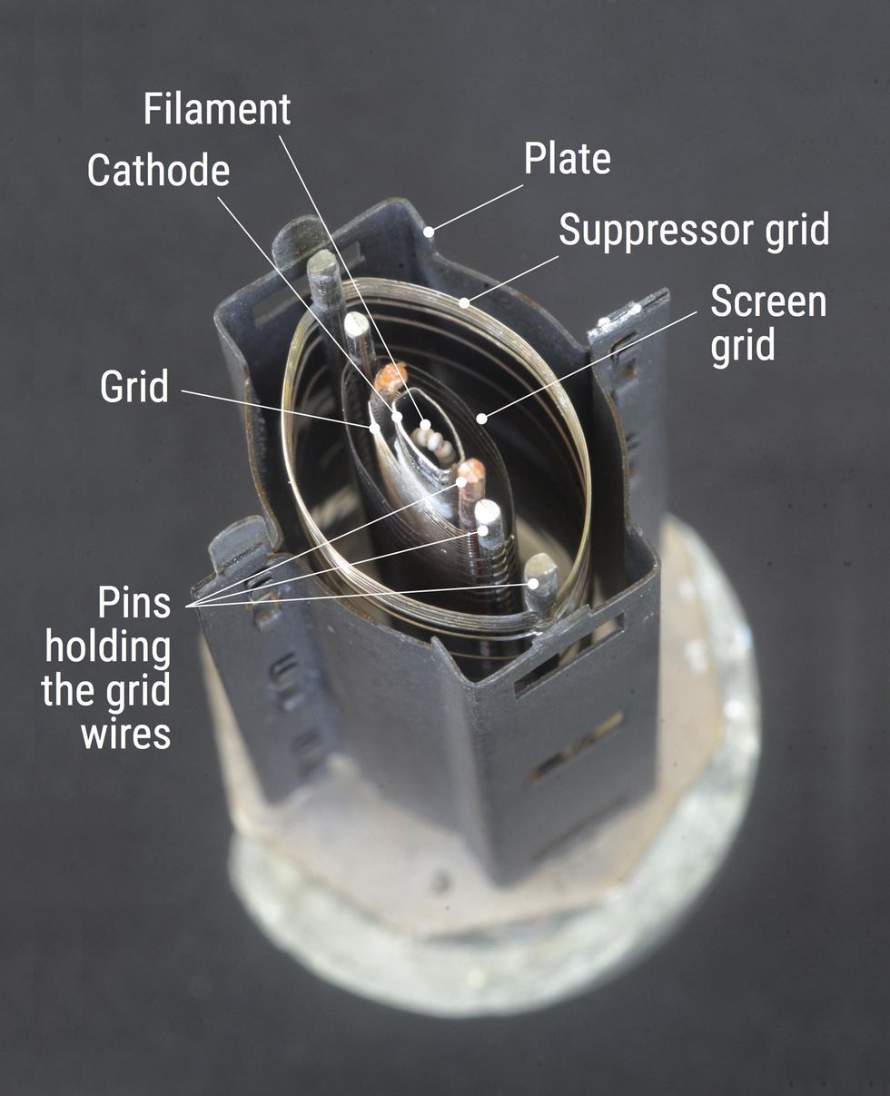
Ever wonder what's behind the glass of your amp's tubes? Well, there's a lot going on in your average pentode or triode—electrons charging around, hitting walls, held at bay. Let's examine an EL84, which is a pentode, as is an EL34 and many other power tubes. That means five elements are at work within the tube (not counting the filament, the heating element tucked inside the cathode). Schematic diagrams like the one below portray tubes as if the cathode is on one side of the glass and electrons flow in a straight line through the tube, with all elements evenly spaced.
In reality, the cathode sits vertically in the center of the tube, and its electrons flow outward. When the cathode is heated, a "space charge" of electrons—a cloud of negative-charged particles—form around it like swarming microscopic bees. Because opposites attract, they are instantly drawn to the high positive-DC voltage of the plate. But the grid stops them. The grid is a wrap of thin wires encircling the cathode that carry your guitar's signal. The grid's at-rest charge appears negative to the cathode, slowing the electron flow. There are two ways for the grid to assume that negative appearance, depending on an amplifier's design: Either the grid is connected to a small negative charge or the cathode has a small positive charge. Electrons don't care which method is used. Just ask 'em.
The cathode, grid, and plate are elements common to triodes (three-element preamp tubes, like a 12AX7) and pentodes. The two additional elements inside the pentode are the screen grid and the suppressor grid. Like the guitar-signal grid, they are wraps of thin wire with mostly open areas that allow flying electrons to reach the plate without being blocked. And like the plate, the screen grid carries a high electron-attracting DC voltage, but its voltage, unlike the plate, is consistent, whereas plate voltage will vary with the signal.
The suppressor grid, the outermost wrap of wire closest to the plate, is connected to the cathode and its job is to repel electrons, which hit the plate and bounce off. The suppressor grid sends them back to the plate to avoid power loss. Beam tetrode tubes like the 6V6, which have four elements, incorporate metal plates that serve a function similar to a pentode's suppressor grid, working to keep the electrons in place.
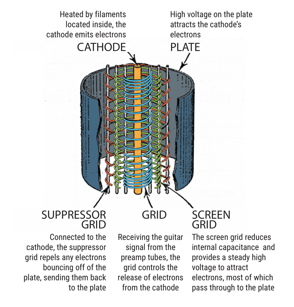
This illustration shows the three grids plus the cathode and plate in a typical pentode tube.
Are Your Tubes Biased?
Sure, you've heard the term bias, but what is it and what does it do for your amplifier? Bias refers to the amount of negative charge the cathode detects on the grid, and it is set to keep the electron flow in check at a happy, medium level. Too negative and not enough electrons will flow when you're playing, so your amp won't produce enough volume and will sound anemic. Too positive you'll be bombarding the plate with too many electrons and overheating it, producing a warm red glow that you don't ever want to see in a tube. At that point, its lifespan could be measured in minutes.
The wattage a tube's plate receives can be determined by multiplying the rate at which electrons flow from the cathode to the plate times the voltage at the plate. The former is measured in amps, and in a cathode-biased amplifier can be calculated by knowing the value of the resistor connected between the cathode and ground, and the voltage drop across the resistor (the "drop" is the voltage measured between one end of the resistor and the other). An EL84 is designed to receive up to 12 watts maximum, and this or just below becomes the target when adjusting the tube's bias. So there you go.
The Many Tasks of Output Transformers
In the main story, we talked about how the output transformer wrangles voltage and works to impede and control the flow of electrons toward the speaker. That's not all it does, but in the process of doing that, it also blocks high voltage DC from streaming through the circuit, which is why you won't get electrocuted touching your speaker connections.
On the primary, or tube, side, the output transformer's impedance rating should more or less match the required impedance for the power tube or tubes being used. That impedance is measured in ohms, on the order of 4,500 ohms for a single EL84 tube, and 8,000 for two in class AB. An output transformer designed for an impedance lower than what the tubes want will lead to too much current flow, overloading the transformer, the tubes, or both. And soon they're kaput.
High voltage on the power tubes' plates also comes from the output transformer, via the rectifier tube or circuit. And that DC voltage is regulated by a large filter capacitor to help smooth out any ripples in voltage.
Yes, Speakers Are Sensitive
There's a rating for how reactive a speaker is to a signal that's typically called sensitivity. Awwww…. A speaker's sensitivity is measured by sending a 1-watt, 1-kHz signal into the speaker and measuring the loudness at 1 meter away.
If 1 watt sounds low, remember that power efficiency of a speaker is also surprisingly low. Most of the power going into a speaker is dissipated as heat. According to Celestion's John Paige, 97 percent of input power becomes heat, and only 2 to 3 percent converts to sound. Years ago, regulations required that speaker voice coils include a fire retardant, because occasionally they'd ignite onstage.
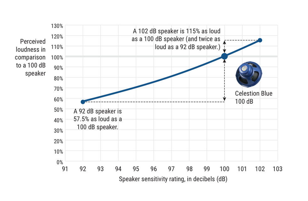
Since speaker sensitivity varies, an easy way to increase or decrease the loudness of an amplifier is to simply change speakers. But here's a quick lesson in sound physics. We measure loudness in decibels, or dB, a unit of sound pressure level, or SPL. Similar to the way we rate the magnitude of earthquakes, decibels are based on a logarithmic scale. So, check out this chart. It illustrates the perceived loudness you might expect for speakers of varying decibels.
And remember, our ears work in a surprising way. To perceive sound as being twice as loud requires an increase of 10 times the sound pressure, or 10 dB. Therefore 70 dB will sound twice as loud as 60 dB, and 80 dB will sound four times as loud as 60 dB. For reference, casual conversation is around 60 dB and 120 dB is jackhammer painful.