
All wiring mods are not created equal. Some add a bit of convenience or a subtle new shading, while others are radical departures that open new creative avenues for the adventurous guitarist.
Consider so-called “vintage" or “'50s-style" wiring, in which the tone pot and cap are connected to the middle lug of the volume pot rather than the usual third lug. Given the sheer number of posts the topic has amassed on guitar-geek sites, you'd think it was an earth-shaking option. Yeah, it's a cool mod that I happen to dig, but really, the sonic benefit is modest: just a bit less loss of brightness when you dial down the volume.
These projects aren't like that. Each one drastically alters your guitar's available tones and the ways you access them. They can literally change the way you play.
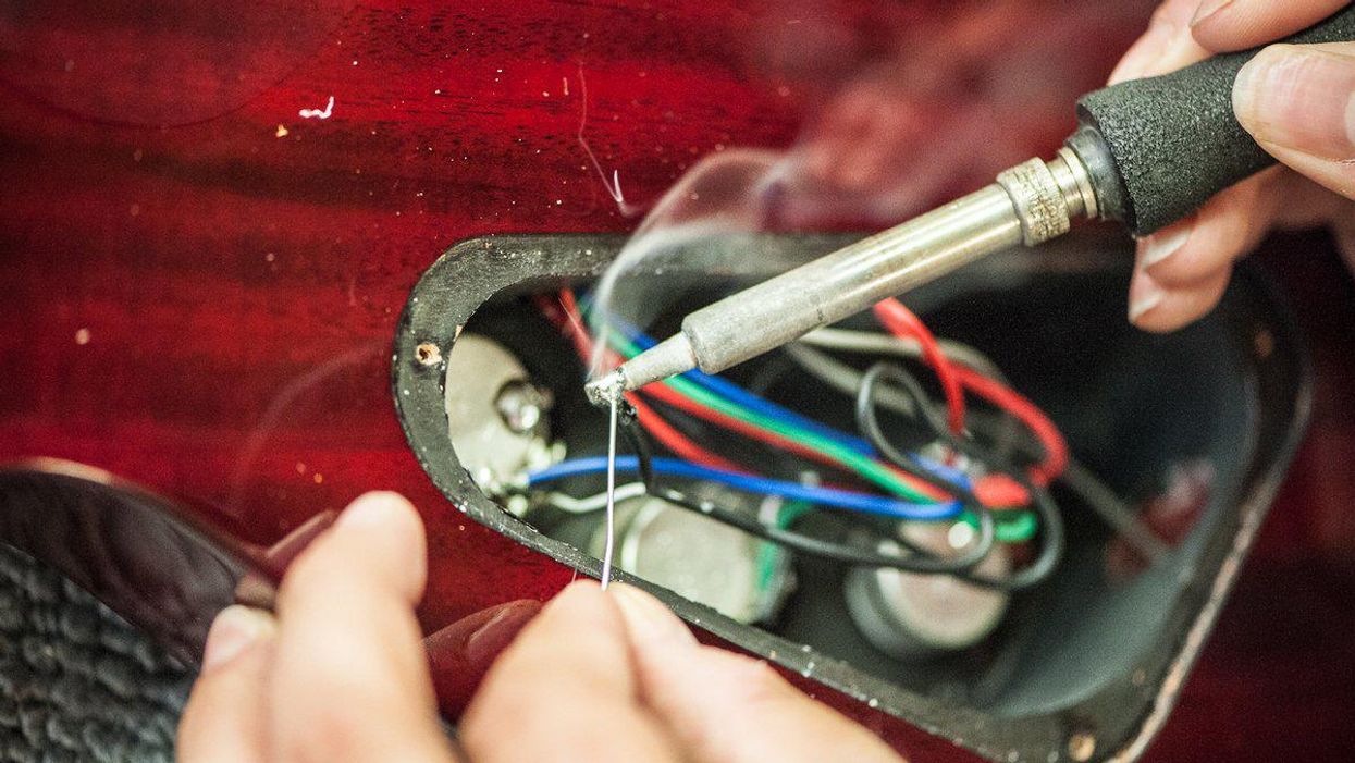
This article assumes you're familiar with basic soldering techniques. If not, check out a few YouTube soldering tutorials. I don't have to remind you to follow all suggested safety guidelines, do I? (Okay—you're reminded.)
Sometimes the best way to add power to your low tones is to remove a bit of bass.
Mod #1: PTB Tone Control
What it is: A variation on the two-band tone circuit that Leo Fender created late in his career for G&L guitars. It employs two tone pots: One cuts highs like a conventional tone control, while the other filters out lows. PTB stands for “passive treble/bass."
The benefits: This mod is a godsend for players seeking greater control over their distortion sounds, especially with humbuckers. When playing clean, the results are relatively subtle. But when you pour on the gain, even tiny adjustments to your signal's bass content can add clarity, punch, and welcome variation to your crunch tones.
Just ask any savvy stompbox builder or low-tuned 7-string player: Sometimes the best way to add power to your low tones is to remove a bit of bass. That's because the lowest frequencies in your signal disproportionately overdrive your amp and effects. Siphoning off just a bit of bass can add clarity and focus. At extreme settings, the filtering can produce sharp, squawking tones akin to those of a '60s treble booster pedal (not a bad thing). If you've ever grappled with high-gain tones that make your amp fart out, here's your flatulence remedy.
The cost: The original G&L scheme calls for alternate pot values, but the project here uses the 500K pots found in most humbucker guitars, so all you need are wire, solder, and a few capacitors. On a three-knob guitar, you wind up with one master volume control and two master tone controls, but you sacrifice individual volume controls for each pickup.On a four-knob guitar, you still have independent volume controls, but you lose the independent tone controls.
How it sounds: Ex. 1a demonstrates the treble-cut control—nothing surprising here. Ex. 1b features the bass-cut. With a clean tone like this, it's a bit subtle, though you can hear the difference if you focus on the low notes. But Ex. 1c adds a vintage-style germanium Fuzz Face with the gain and volume maxed. With the guitar's tone control wide-open, the signal easily overpowers my vintage Fender brownface—your typical Fuzz Face fart. As I gradually trim bass via the guitar, the tone acquires greater punch and clarity. I remain on the neck pickup throughout—the only thing changing is the guitar's bass pot setting. The extreme-cut settings near the end of the clip may sound harsh in isolation, but they can be perfect in a band context. At the end of the clip I max the bass pot again to underscore how much the tone has changed. It ain't subtle.
How it works — Diagram 1a depicts Leo's original schematic:
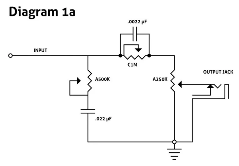
The signal from your pickups or pickup selector gets routed to two tone pots. The 500k pot and .022 µF capacitor provide a conventional treble-cut control. Meanwhile, the 1M pot and smaller .0022 µF cap filter out lows. (Pay careful attention to the zeros and decimal points in those cap values!) The treble cut creates its effect in the usual way: by diverting signal to ground. But the bass cut doesn't go to ground at all—the low-filtering cap is inline with your signal. Its output goes to the volume pot (250k in the original). Clever!
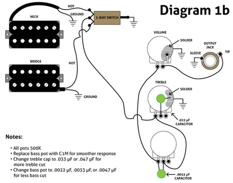
Diagram 1b shows my adaptation for three-knob humbucker guitars, using the extant 500k pots:
For visual clarity, I've indicated ground connections with a down-facing triangle. As you probably know, all ground wires must be electronically connected to each other. (One convenient method is to solder all pickup ground wires, the output jack ground, the pickup selector ground, and the bridge's ground wire to the back of the volume pot, and then run a jumper wire to ground the treble control. In conventional wiring, all pots must be grounded, but here, it's not necessary to ground the bass pot.)
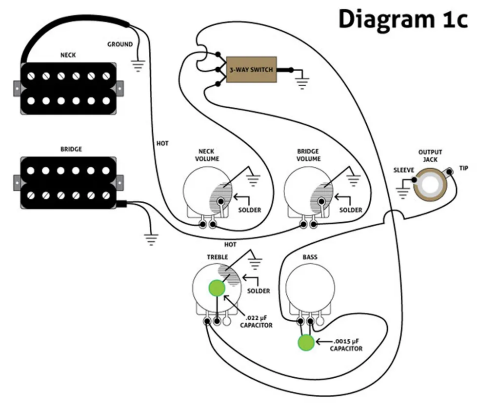
Diagram 1c is a version for four-knob guitars, such as traditional Les Pauls. The only difference: On three-knob guitars, the signal usually goes from the pickups to the pickup selector to the pots. But on four-knob guitars, the volume pots are upstream from the pickup selector to permit independent volume control per pickup.
DIY walkthrough: You don't necessarily need to perform the steps in this order—it's just one method.

Photo 1a
Since I have no idea how your guitar is currently wired, I've started with a fresh set of pots. My demo guitar is a three-knob Hamer 20th Anniversary, which has its pickup selector in the control cavity alongside the pots [Photo 1a.]
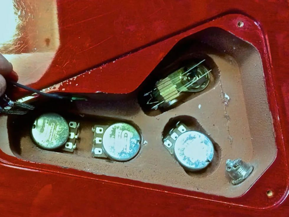
Photo 1b
In Photo 1b I've completed the ground connections as described above, though I've connected the output jack's ground to the back of the treble pot. The white wire is the pickup selector output, connected here to lug 3 of the treble pot. (Remember: When viewing pots from the back, lugs down, lug 3 is on the left, and lug 1 is on the right.) This wire usually connects to lug 3 of the volume pot, but this circuit routes the signal through the bass pot first.
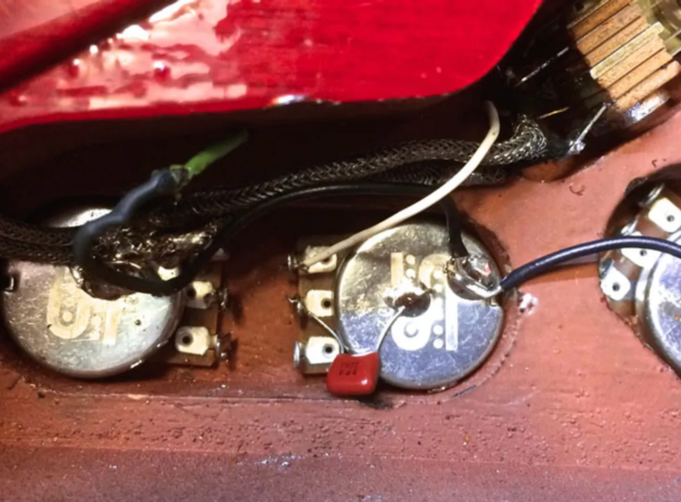
Photo 1c
In Photo 1c I've added the treble-cut capacitor between lug 2 of the treble pot and ground. I used a .022 µF (also known as a 223). For more cut, try a larger value, such as .033 µF (333) or .047 µF (473). The larger the cap, the greater the cut.
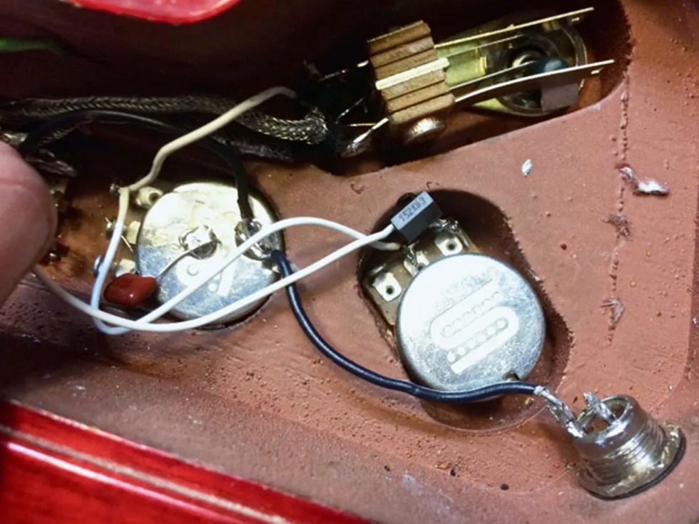
Photo 1d
Photo 1d adds the bass-cut components. Since the output from the pickup selector must feed both tone pots, I've run a wire from lug 3 of the treble pot to lug 3 of the bass pot. I've added a .0015 µF (152) cap between lugs 3 and 2. Here, pot values work in the opposite direction: the smaller the cap, the greater the bass cut. If the .0015 µF sounds too extreme, try stepping up to a .0022 µF (222). I've added a wire to the bass pot's lug 2, which connects to the volume pot's lug 3. Connect the volume pot's lug 2 to the output jack, and you're done.
A reverse-log bass pot? While you can get fine results using your guitar's extant pots, the original G&L circuit calls for a 1M reverse-log pot (the “C" in C1M signifies reverse-log). With a standard audio-taper pot, the effect comes on quickly near the top of the pot's range. With a reverse-log pot, you get a gradual onset of the bass cut that may be easier to fine-tune. The problem is, it's almost impossible to find a C1M pot in a standard 24 mm format. You can get a 16 mm version from stompbox parts suppliers, but it won't work in Les Pauls requiring long pot shafts. After experimenting with various options, I've gone back to a standard 500k pot, because when I reach for that control, I usually want the lows to evaporate quickly.
Mod #2: Nashville Strat
What it is: A Stratocaster version of “Nashville wiring," a trick Telecaster mod popularized by Music City's session cats. Some Tele players add a third pickup (plus a blend knob), expanding the range of combined-pickup tones. The same wiring performs brilliantly in a Strat—without the cost and hassle of installing a third pickup.
The benefits: Access to a stunning array of combined-pickups sounds, including the outer pickups together—a gorgeous color not available from conventional Strat wiring. Not only can you choose between four cool combined sounds, but you can also vary the blend for subtler effects than those of a traditional Strat's 2 and 4 positions.
No matter what position the pickup selector is in, you always have access to the so-called “out of phase" sounds via the blend pot.
The costs: This mod requires a Tele-style 3-position pickup selector in lieu of a Strat's usual 5-position switch. You also sacrifice the sound of the middle pickup alone. The middle knob becomes a pickup blend control, while the third knob serves as a global tone control.
How it sounds: Ex. 2 showcases an assortment of combined-pickup tones not available on a conventional Strat. (The demo guitar is a “parts" Strat with three lipstick-tube pickups. While their character differs from those of traditional Strat pickups, it's a good representation of the range of available tones.) You also have access to the traditional position 1 and 5 tones.
Playing guitars wired this way changed how I view combined-pickup sounds. Whatever position the pickup selector is in, you always have access to the so-called “out of phase" sounds via the blend pot. The blend control becomes something like a camera's aperture setting: In minimum position, sounds are direct and crisp. As you advance the knob, tones become softer, prettier, and more diffuse. I find this to be a more musical and intuitive approach to tone sculpting.
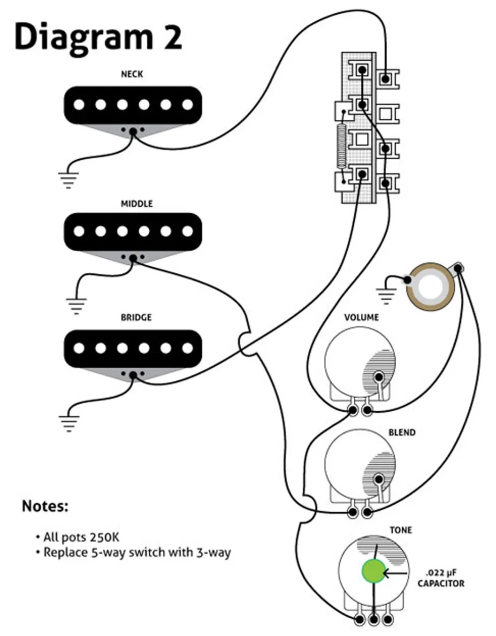
Diagram 2
How it works: The neck and bridge pickup are wired as on a traditional Tele, with the pickup selector's middle setting combining the two pickups. Meanwhile, the middle pickup is routed directly to the output jack, bypassing the tone and volume controls (Diagram 2).
That may seem counterintuitive: Wouldn't you want the tone control to affect both pickups in combined-pickup settings? But it just seems to sound better this way. Rolling back the treble on combined-pickup tones tends to rob them of their cool phase-cancelled character. This way, tones still get darker/warmer when you dial back the treble, yet retain a nice airiness. Try it and see!
DIY walkthrough: In Photo 2a I've replaced the Strat's 5-way pickup selector with a Tele-style 3-way. I've threaded a wire through the two leftmost lugs of the selector's spring side and the two rightmost lugs on the opposite side. Additionally, I've connected the bridge and neck pickups as shown in Diagram 2.
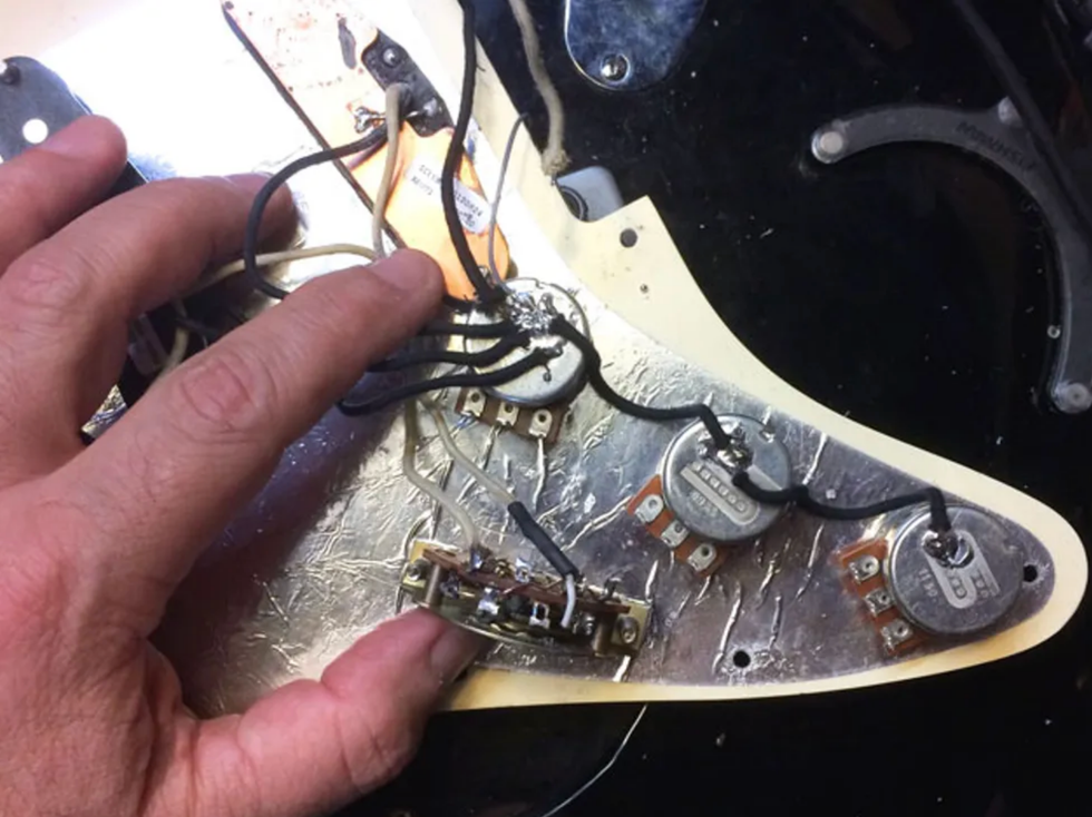
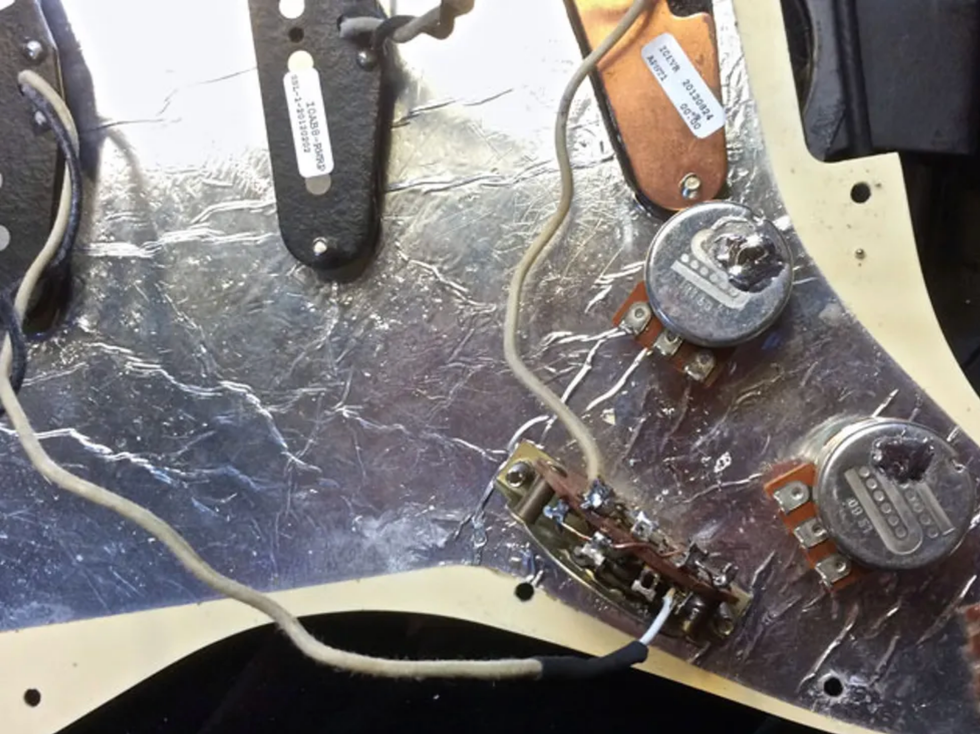
Photo 2b
In Photo 2b I've added all the ground connections. The three pickup ground wires, output ground, and bridge ground are all soldered to the rear of the volume pot, with additional wires grounding the blend and tone pots. (All pots must be grounded in this circuit. It doesn't matter where they connect physically, so long as they connect electronically.)
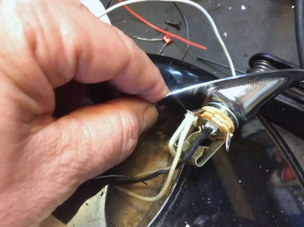
Photo 2c
You must connect both the volume and blend control outputs to the output jack. In Photo 2c I've removed the jack plate to install a second wire that will connect to lug 2 of the blend pot. (Alternately, you could add a Y-joint inside the main control cavity, reinforcing the connection with heat-shrink tubing.)
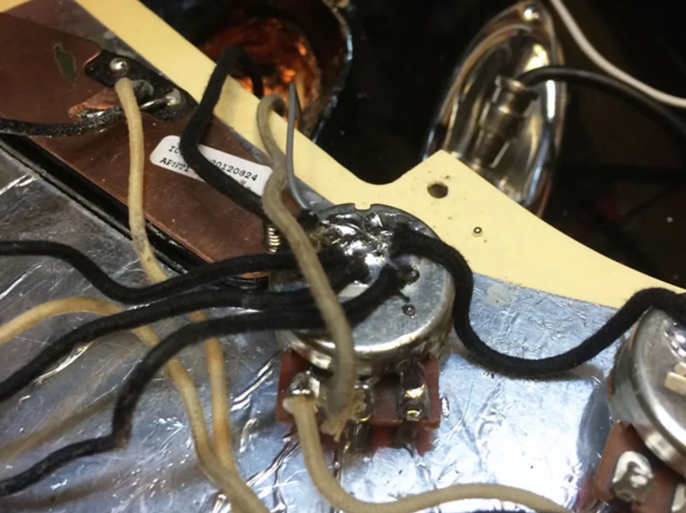
Photo 2d
Photo 2d shows the volume pot connections. One output jack wire connects to lug 2, while the pickup selector output (the rightmost lug on the non-spring side, as viewed in this orientation) connects to lug 3. Lug 1 is bent and soldered to the side of the pot for a ground connection, per usual.
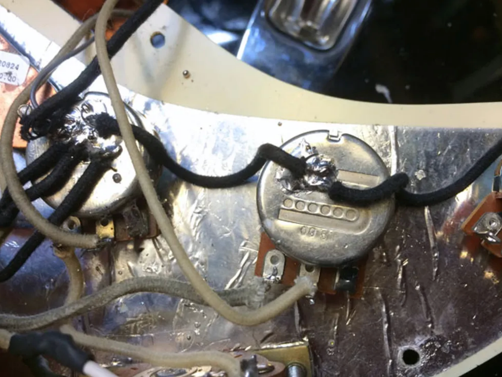
Photo 2e
The blend control wiring appears in Photo 2e. The hot wire from the middle pickup connects to lug 3, bypassing the tone and volume controls. The second output jack wire connects to lug 2.
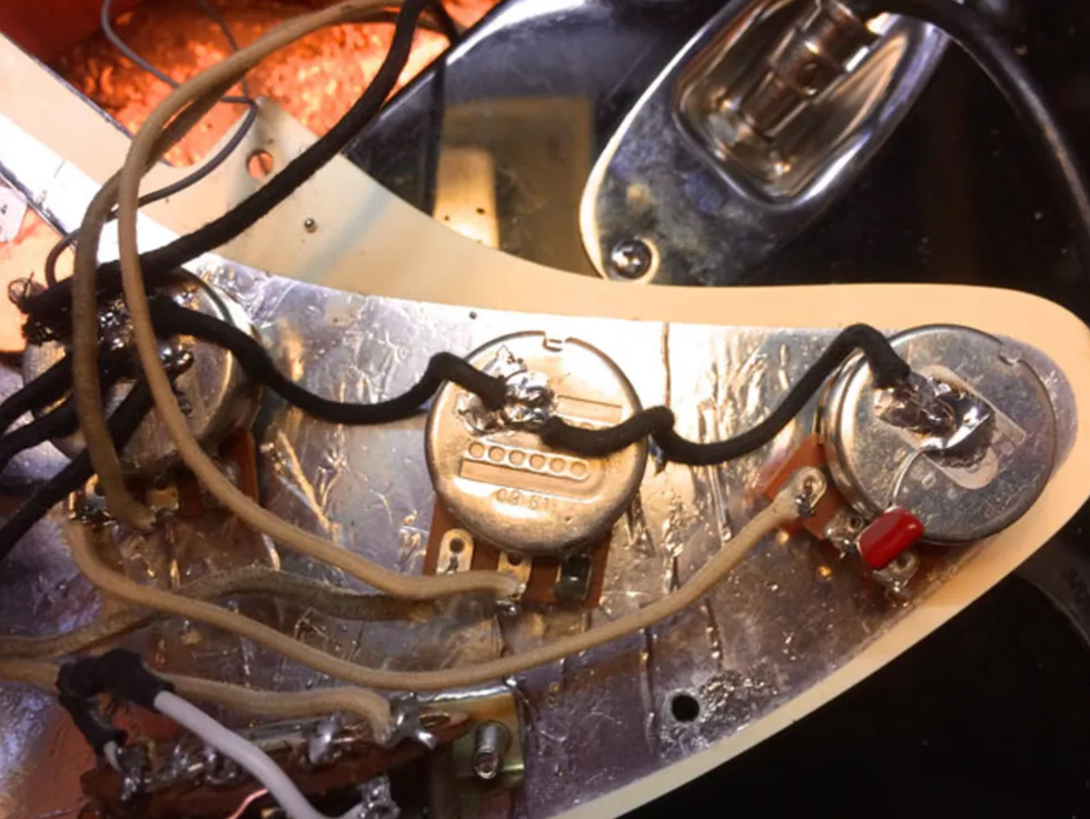
Photo 2f
Photo 2f shows the tone pot wiring. Lug 3 connects to the volume pot's lug 3. Solder one end of the tone-cut capacitor to lug 2, and the other to the back of the pot, grounding it. I've used a .022 µF (223), a standard value, though you can step up to .033 µF (333) or .047 µF (473) for a stronger effect—the larger the cap, the greater the treble cut. If you like the sound of your current tone cap, just reuse it here. And that's it!
Bonus bridge pickup tip: Like many Strat users, I have a love/hate relationship with the traditional bridge pickup. It works great when you want a clear, piercing sound, but tends to be short on mass. Some players remedy this by installing humbuckers or other higher-output pickups in the bridge position. But instead of trying to coax Gibson tones from a Strat bridge pickup, I prefer a Tele-style bridge pickup sized for Strats, such as the excellent Seymour Duncan Twang Banger. With its Tele-style metallic base plate, it provides tough, edgy tones with more mass than traditional Strat pickups—without relinquishing that fine Fender sizzle.
Capacitor Cheat Sheet
Are you confused by capacitor nomenclature? Join the club!
To gain a thorough understanding of how caps work and how they're labeled, Google “capacitor values." In the meantime, here's a handy cheat sheet showing the most common cap values for guitar applications.
The first number in each pair is the value in farads, the unit used to measure capacitance. The “µF" signifies microfarad—a millionth of a farad. People often substitute “uF" for “µF" to avoid the hassle of using a Greek letter. It's also sometimes written as “MFD."
The second number in each pair is the shorthand way of indicating these values, and that's usually the number you find on the caps themselves.
The values appear in ascending order. The ones highlighted in green are typical values for conventional treble-cut tone controls. The ones in red are good starting values for the bass-cut controls in these projects. If a particular value doesn't work for you, just step up or down in value till you hear what you like.
- .0001 µF (101)
- .00015 µF (151)
- .00022 µF (221)
- .00033 µF (331)
- .00047 µF (471)
- .00068 µF (681)
- .001 µF (102)
- .0015 µF (152)
- .0022 µF (222)
- .0033 µF (332)
- .0047 µF (472)
- .0068 µF (682)
- .01 µF (103)
- .015 µF (153)
- .022 µF (223)
- .033 µF (333)
- .047 µF (473)
- .068 µF (683)
- .1 µF (104)
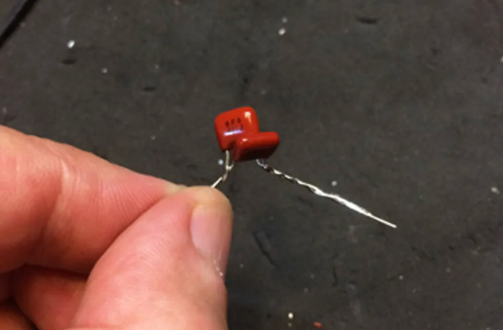
Capacitor hacks. If you find yourself lacking the perfect cap value, remember that you can wire together two caps in parallel, as shown in Photo 1e.
Mod #3: Varitone Variation
What it is: The original Varitone, which appeared in such vintage Gibsons as the ES-345 and ES-355, is a controversial circuit. In lieu of standard treble-cut caps and pots, it employs a rotary switch, with each position routed through a different-sized capacitor. It also calls for an inductor, which creates a series of notch filters. (In other words, the circuit doesn't remove all signal above a certain frequency, but only a certain amount above and below that frequency.)
While the Varitone has its fans, it was never very popular. Detractors argue that it sucks tone, and its settings are too thin and “quacky" for many players. But even if you don't dig the original Varitone sounds, you can use its general concept to great effect. (For example, if you omit the inductor, you lose a bit of the peaky resonance that alienates some players.)
You might want to deploy your pots for something other than the traditional uses—controlling onboard effects, for example.
The benefits: Multiple capacitor schemes can provide instant access to a wide range of favorite settings, plus others not available from a conventional tone control. Instead of fiddling with a pot, you can leap to the desired tone with the flick of a switch.
The cost: When you replace a tone pot with a tone switch, you lose access to settings that “fall between the cracks" of the switch positions. You also need various switches and caps, depending on how you configure the mod.
How it sounds: I wired up a multi-cap, two-switch tone circuit in a “parts" Jazzmaster with P-90s and flatwound strings. Ex. 3a demonstrates my three treble-switch settings. You hear my three bass-cut settings in Ex. 3b. As with the PTB mod, the variations can be subtle with clean tones. But when I add a custom germanium booster in Ex. 3c, everything gets much more dramatic. The entire clip is performed on the bridge pickup—the only things changing are the tone switch settings.
Multi-capacitor switches let you choose your own set of cutoff frequencies, but once a capacitor is engaged, it's engaged all the way. So instead of cutting varying amounts of signal at a fixed frequency, you cut fixed amounts of signal at varying frequencies.
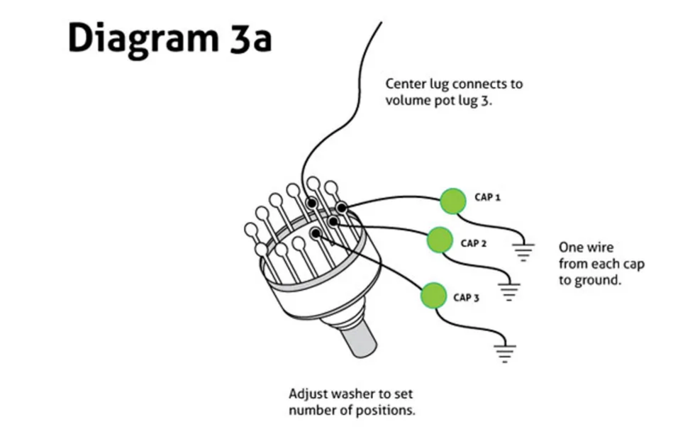
Diagram 3a
Diagram 3a shows the basic idea. The center lug of the rotary switch connects to lug 3 of your volume pot, like a conventional tone control. You weave capacitors of escalating value through the lugs lining the pot's perimeter, so that when you move the switch, a new cap is engaged. The other terminals of the caps go to ground—usually by bundling them together, wrapping them in heat-shrink tubing, and soldering the assembly to a ground point. (Most rotary switches let you specify the number of active positions via a notched washer on the pot's shaft.)
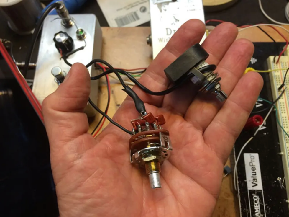
Photo 3a
This is a cool mod, but there's one good reason not to bother: Someone beat us to it. This is precisely how Stellartone's ToneStyler replacement tone pots work. They're fine products, and if you can afford the cost (models start at $75 street), I recommend them. Photo 3a shows my homemade part alongside a ToneStyler—which would you rather put in your guitar? (Plus, I hate the stiff, clunky feel of the commonly available rotary switches.)
Instead, let's look at an approach that uses mini-switches rather than a big rotary switch. These limit you to three settings per switch, as opposed to as many as a dozen from a rotary switch. But there are at least two good reasons to go this route: It's easy to install mini-switches on almost any guitar, while adding pots can be problematic. And there are times when you might want to deploy your pots for something other than the traditional uses—controlling onboard effects, for example. (Which, by the way, is the subject of an upcoming Premier Guitar article.)
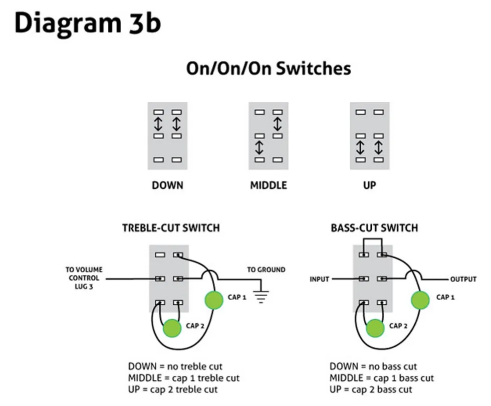
Diagram 3b
There are many types of mini-switches, but this project calls for the on/on/on DPDT variety, which have two rows of solder lugs and three switch positions. Diagram 3b shows how they work—and how to configure them as treble-cut and bass-cut controls.
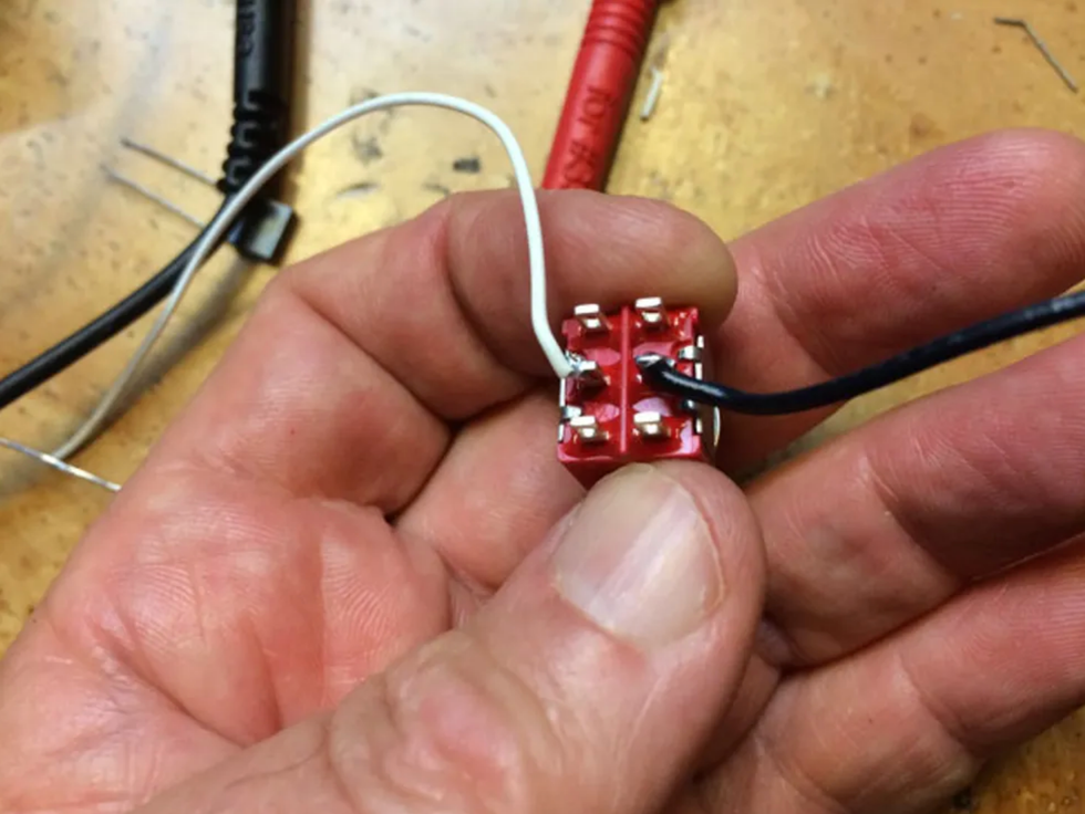
A 3-position treble-cut switch. For a treble-cut switch, connect the input to the left-center lug, and a ground wire to the right-center one, as shown in Photo 3b.
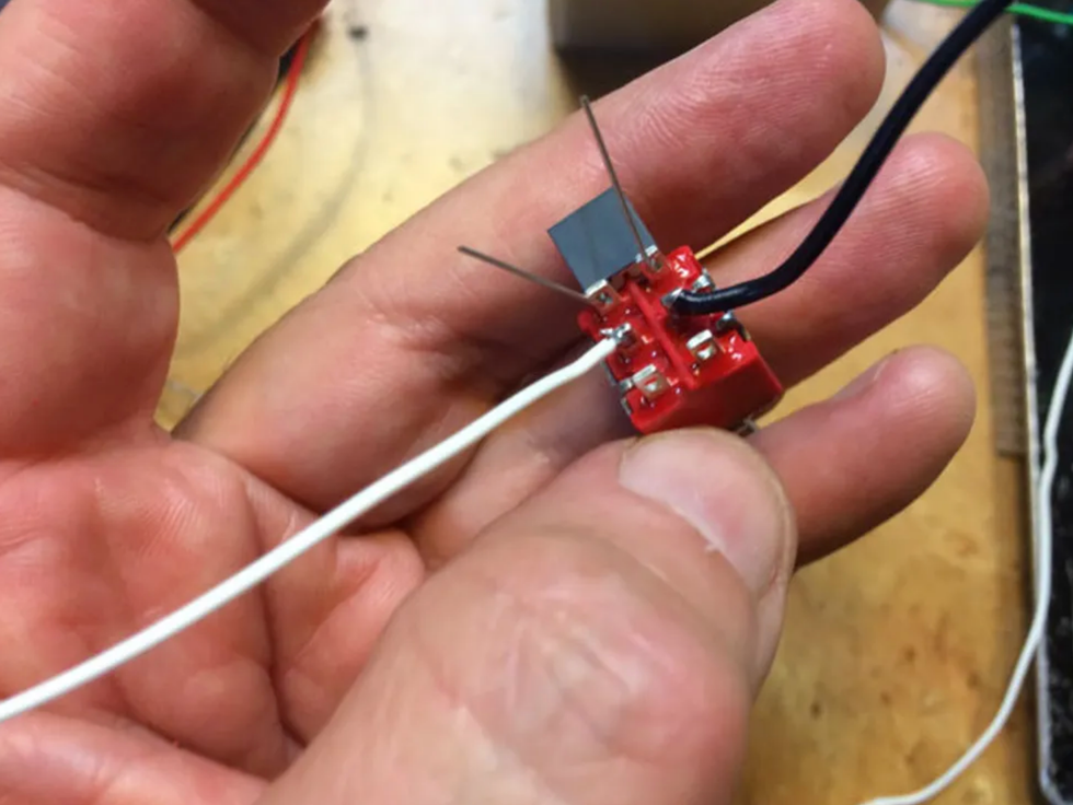
Photo 3c
With the switch in the down position, the signal gets routed through whatever you connect to the top two lugs. In Photo 3c I've threaded the first of two treble-cut caps—a .022 µF (223)—through the top lugs.
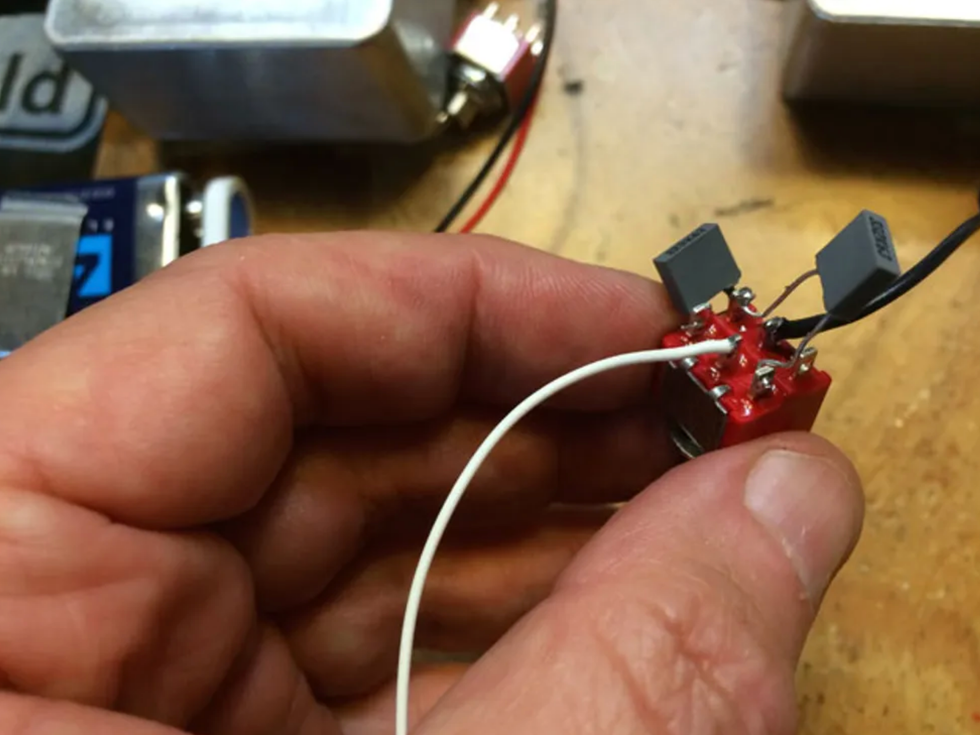
Photo 3d adds a second tone cap—a .0033 µF (332)—between the lower-left lug and the upper-right one. This is engaged when the switch is in the middle position. There's nothing between the two lower lugs—when the switch is in the up position, no tone cap is active, and your tone is wide-open.
My cap values are customized for the way I tend to use treble-cut controls: either to take off a bit of edge, or to get very dark. Configured this way, I get an open sound when the switch is down. In the middle position, there's a slight treble cut from the relatively small .0033 µF cap. And in the up position, I get a much darker tone via the larger .022 µF cap. You can vary these values to taste—just remember that larger caps cut more treble.
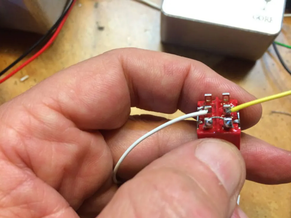
Photo 3e
A 3-position bass-cut switch. The wiring is similar for a bass-cut switch, but with one key difference: While the treble-cut routes signal to ground, a bass-cut must be inserted within the signal flow, just as in the PTB project above. The signal comes in via the left-middle lug, and exits via the right-middle one, as shown in Photo 3e. Also, I've added a jumper wire between the two lower lugs, so when the switch is in the up position, signal is routed through the switch without encountering a capacitor. (To reverse the orientation, just flip the switch 180 degrees.)
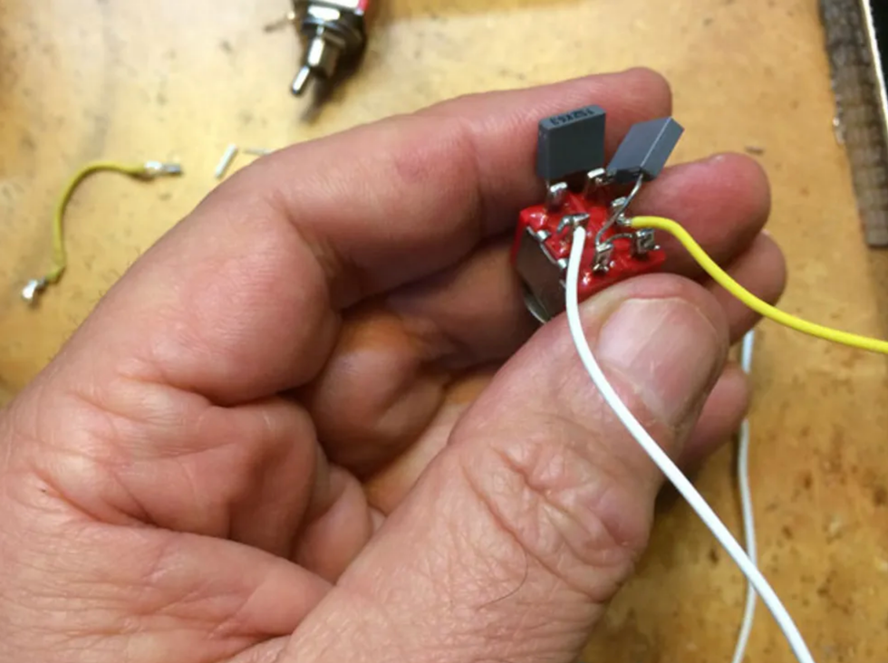
Photo 3f
In Photo 3f, I've added two capacitors, as in the treble-cut circuit. I used a .0033 µF (332) for a slight bass cut in the middle position, and a .0015 µF (152) for a more extreme cut. Choose your own cap values, bearing in mind that the smaller the cap value, the greater the bass cut.
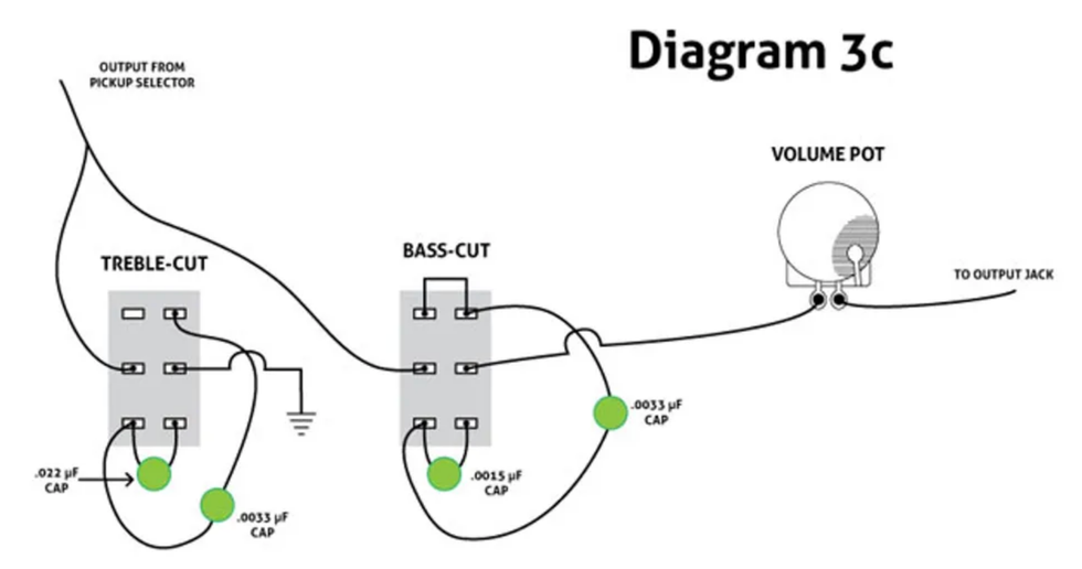
Diagram 3c
Finally, Diagram 3c shows my two-switch/six-setting tone control as heard in Ex. 3c. With the values I used, the result is similar to the PTB mod above, but with two added advantages: I can toggle quickly to the exact tone I desire. And by drilling two small holes in my pickguard to accommodate the mini-switches, I freed up my former tone pot for another task: controlling an onboard booster.
Mods à la mode. I urge adventurous solder jockeys to try all three mods. They're easily reversible (except for pickguard drill holes), and even if you don't dig the results, I'd be surprised if the process didn't suggest alternate ideas more to your taste. You'll learn volumes about guitar electronics as you uncover your ultimate mod.
[Updated 11/30/21]